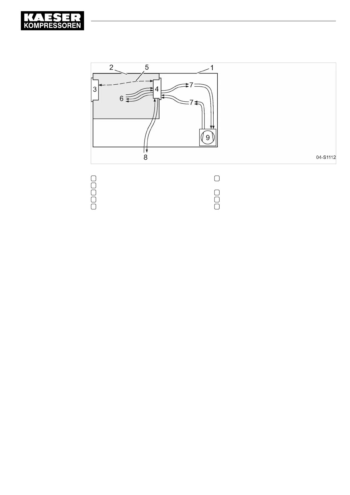
Fig. 4 System structure
1 Machine enclosure
2 Control cabinet
3 Main Control System
4 Input/output module
5 I/O bus
6 Inputs/outputs in the interior of the control
cabinet
7 Inputs/outputs in the interior of the blowers
8 Inputs/outputs for external sensors
9 Compressor
Function
The control and regulating function allows:
■ Automatic changeover of the machine from LOAD to IDLE or READY.
■ OFC/SFC: Optimum utilisation of the drive motor in relation to the user's actual air demand.
■ Automatic restart of the machine after a power failure (can be activated).
The monitoring function allows:
■ Supervision of all maintenance-relevant components via the maintenance interval counters.
■ Display of warning and maintenance messages for due maintenance on the display of
the SIGMA CONTROL 2.
The protective function allows:
■ Automatic machine shutdown on alarms that may lead to damage to the machine, e.g. overcur‐
rent, overpressure, overtemperature.
5 Design and Function
5.2 The controller
No.: 901700 10 E
Service Manual Controller
SIGMA CONTROL 2 BLOWER ≥ 2.5.3
21
 Loading...
