5.4.1 Operating mode
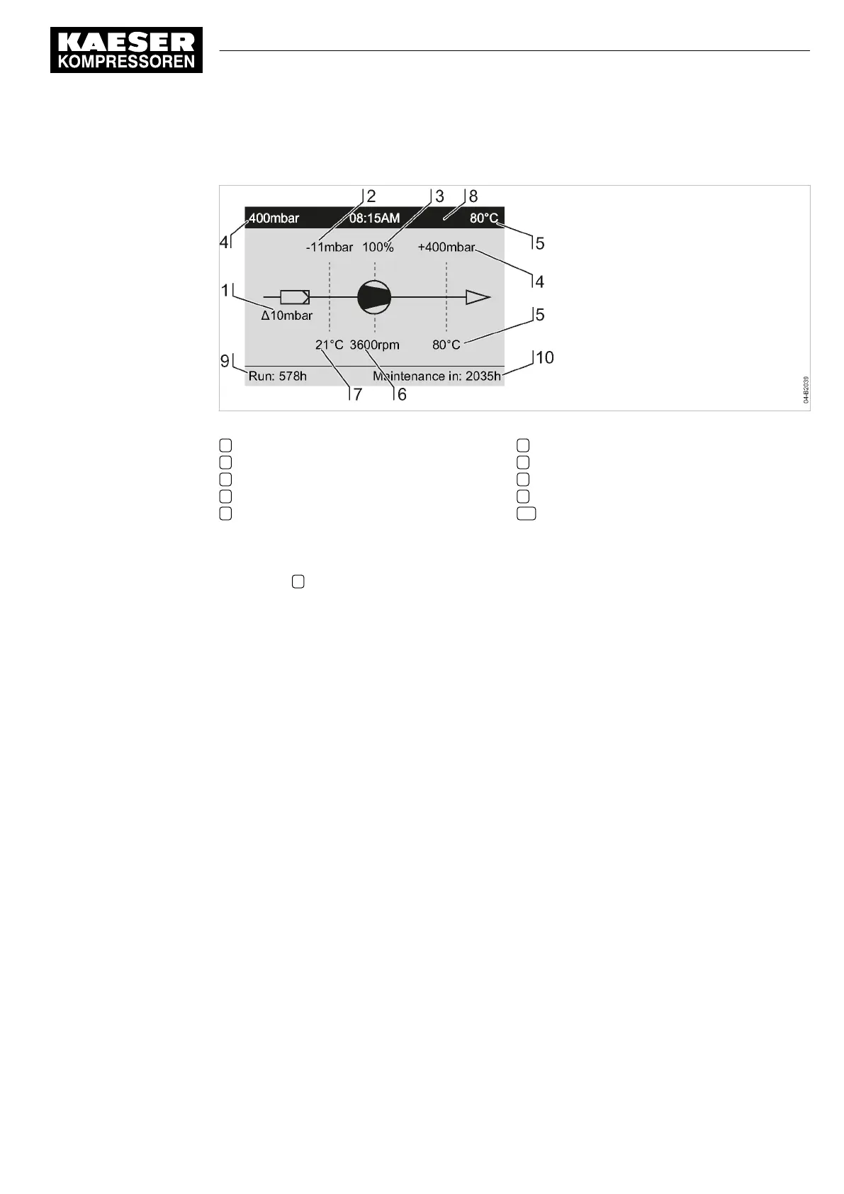
Fig. 8 Operating mode
1 Air filter
2 Inlet pressure p1
3 OFC/SFC: Drive motor’s duty cycle in %
4 Final pressure p2
5 Discharge temperature T2
6 OFC/SFC: Speed compressor
7 Intake temperature T1
8 Header
9 Cut-in period
10 Time until the next maintenance
Header
The header 8 is the topmost line on the display. It is always shown as white text on a black back‐
ground.
The following parameters are displayed permanently in the header:
■ Final pressure p2
■ Time
■ Discharge temperature T2
Lines 2 to 7: Pipe and instrument flow diagram
Display lines 2 to 7 display the current machine state as a pipe and instrument diagram (see Fig. 8)
or a menu text.
Line 8: Machine state
The following parameters with their current values are displayed in line 8:
■ The hours during which the machine was activated
■ Remaining desiccant service life of the machine until the next maintenance.
5 Design and Function
5.4 Display
No.: 901700 10 E
Service Manual Controller
SIGMA CONTROL 2 BLOWER ≥ 2.5.3
25
 Loading...
