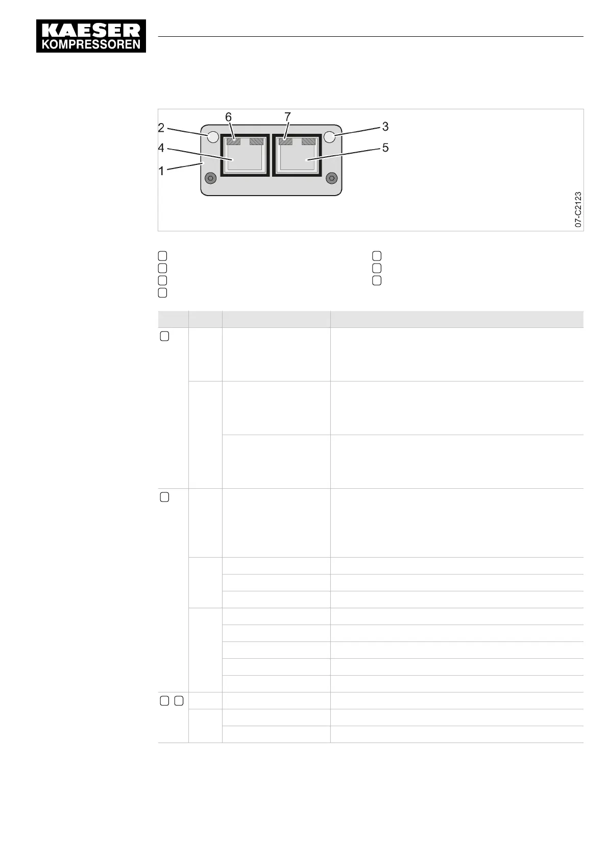
Fig. 40 PROFINET communication module – LEDs and interface
1 Communications module
2 LED NS: Network status
3 LED MS: Module status
4 PROFINET Port 1
5 PROFINET Port 2
6 LED connection status Port 1
7 LED connection status Port 2
LED Colour State Meaning
2 NS off Offline
■ Module without voltage
■ No communication with the IO controller
Green illuminates continuously Online (RUN)
■ Module connected to bus, communication is running
■ IO controller in RUN mode
flashes Online (STOP)
■ Module connected to bus, communication is running
■ IO controller in STOP mode
3 MS off Not initialised
■ Module without voltage
■ Module in "Setup" status
■ Module in "NW-INIT" status
Green illuminates continuously Module in operation
flashes 1:1 (on:off) Diagnostic data available
flashes 2:1 (on:off) Is used by Engineering Tools to identify the network node
Red illuminates continuously Module in "EXCEPTION" status
flashes 1:1 (on:off) Configuration fault
flashes 2:1 (on:off) IP address not set
flashes 3:1 (on:off) Station name not set
flashes 4:1 (on:off) Internal error
6 , 7 off No connection.
Green illuminates continuously Connection established, no communication
flashes Communication in operation
Tab. 92 PROFINET communications module – Interpretation of LEDs
9 Operation
9.8 Communication modules
No.: 901700 10 E
Service Manual Controller
SIGMA CONTROL 2 BLOWER ≥ 2.5.3
147

 Loading...