LED Colour State Meaning
6 , 7 off No connection.
Green illuminates continuously Connection established, 100 Mbit/s
flashes Communication running, 100 Mbit/s
Yellow illuminates continuously Connection established, 10 Mbit/s
flashes Communication running, 10 Mbit/s
Tab. 90 Modbus TCP communications module – Interpretation of LEDs
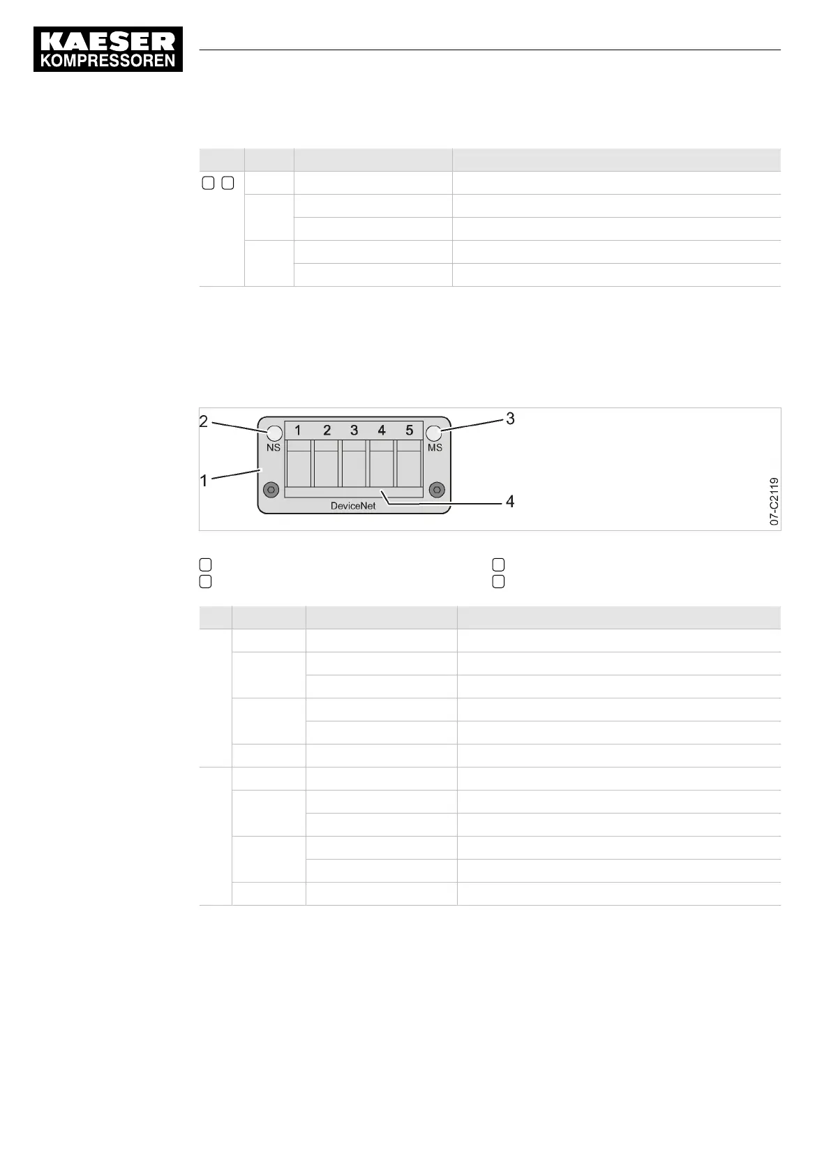
9.8.4 Display at the DeviceNet module
The communication module features LEDs providing information about the module status.
Fig. 39 DeviceNet communication module – LEDs and interface
1 Communications module
2 LED NS: Network status
3 LED MS: Module status
4 DeviceNet connection plug
LED Colour State Meaning
NS off Module without voltage/not connected to bus
Green flashes Module connected to bus
illuminates continuously Module connected to bus, communication is running
Red flashes Time-out, communication interrupted
illuminates continuously Connection fault
Red/Green alternating Self test
MS off Module without voltage/deactivated
Green illuminates continuously Module in operation
flashes Incomplete configuration, commissioning required
Red flashes Recoverable error
illuminates continuously Unrecoverable error
Red/Green alternating Self test
Tab. 91 DeviceNet communications module – Interpretation of LEDs
9.8.5 Displays at the PROFINET module
The communication module features LEDs providing information about the module status.
9 Operation
9.8 Communication modules
146
Service Manual Controller
SIGMA CONTROL 2 BLOWER ≥ 2.5.3 No.: 901700 10 E
 Loading...
