2. Press «Enter».
The display for the message type flashes.
3. Use «Up» or «Down» to set the message type.
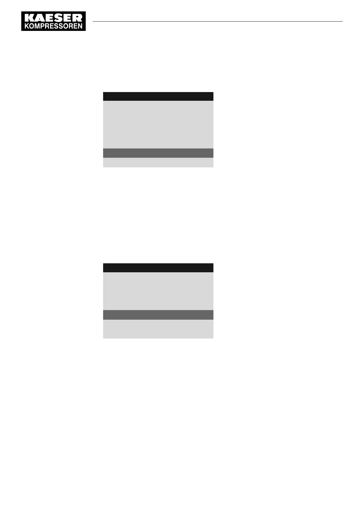
4 0 0 m b a r 0 8 : 1 5 A M 8 0 ° C
Header
5.10.2.1 External message 1
Menu
External message 1
Message text
DI1.07 ok ☑
Input selected
td: 0s ¦ Logic : +
DOR1.04 ☐
Warning ☑
Example: Warning message type
4. Press «Enter».
The message type is set.
8.8.2.7 Assign and activate the output
1. Use «Up» or «Down» to select the
DOR
line.
2. Press «Enter».
The
DOR
output display flashes.
3. Select the output with the «Up» and «Down» keys.
4. Press «Enter».
The setting is applied.
4 0 0 m b a r 0 8 : 1 5 A M 8 0 ° C
Header
5.10.2.1 External message 1
Menu
External message 1
Message text
DI1.07 ok ☑
Input selected
td: 0s ¦ Logic :
DOR1.04 ☑
Output is selected and activated
Warning ☑
Example: Warning message type
5. Press the «Right» key.
6. Press «Enter».
The check box assigned to the output flashes.
7. Press the «Up» key.
The check box is activated.
8. Press «Enter».
The output is assigned and activated.
Result The signal at the DI digital input is available as
External message 1
and as output signal at the
selected DOR output.
8 Initial Start-up
8.8 Setting input and output signals
No.: 901700 10 E
Service Manual Controller
SIGMA CONTROL 2 BLOWER ≥ 2.5.3
125
 Loading...
