GPIB bus operation and reference
Introduction
The following paragraphs contain information about connecting to and using the GPIB
(IEEE-488) bus.
GPIB bus standards
The GPIB bus is the IEEE-488 instrumentation data bus with hardware and programming
standards originally adopted by the IEEE (Institute of Electrical and Electronic Engineers) in
1975. The Model 2010 multimeter conforms to these standards:
• IEEE-488-1987.1
• IEEE-488-1987.2
This standard defines a syntax for sending data to and from instruments, how an instrument
interprets this data, what registers should exist to record the state of the instrument, and a group
of common commands.
• SCPI 1991 (Standard Commands for Programmable Instruments)
This standard defines a command language protocol. It goes one step farther than
IEEE-488-1987.2 and defines a standard set of commands to control every programmable aspect
of an instrument.
GPIB bus connections
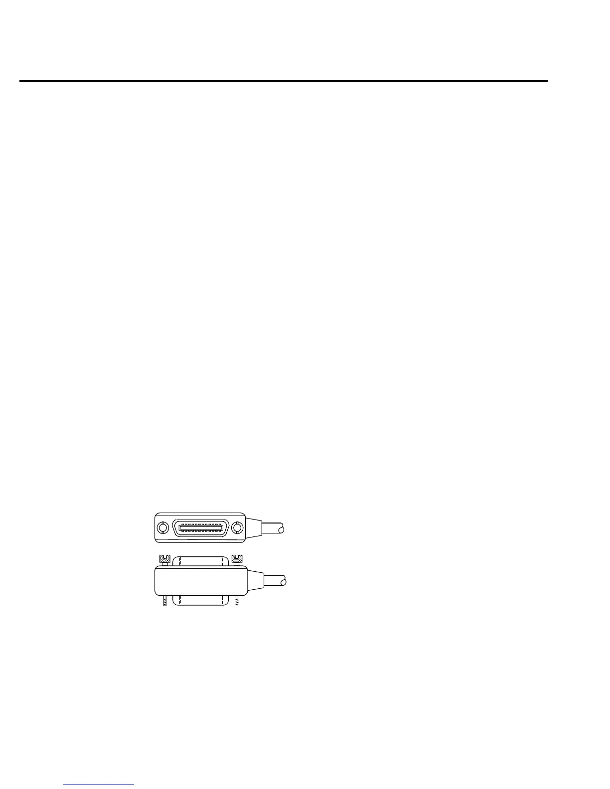
To connect the Model 2010 Multimeter to the GPIB bus, use a cable equipped with standard
IEEE-488 connectors as shown inFigure 4-2.
To allow many parallel connections to one instrument, stack the connector. Two screws are
located on each connector to ensure that connections remain secure. Current standards call for
metric threads, which are identified with dark-colored screws. Earlier versions had different
screws, which were silver-colored. Do not use these types of connectors on the Model 2010
Multimeter, because it is designed for metric threads.
Figure 4-3 shows a typical connecting scheme for a multi-unit test system.
gure
-
EEE-488 connector
4-8 Remote Operation

 Loading...


