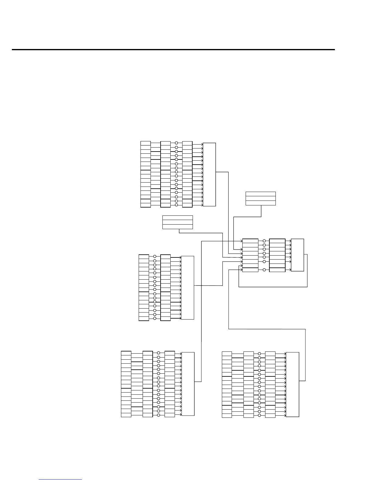
Status structure
See Figure 4-5 for the Model 2010 Multimeter’s status structure. Instrument events, such as
errors, are monitored and manipulated by four status register sets. Notice that these status
register sets feed directly into the Status Byte Register. More detailed illustrations of these
register sets are provided in Figure 4-5 through Figure 4-9.
0
2
3
5
6
Cal
7
9
10
11
12
13
14
15
Questionable
Condition
Register
(Always Zero)
0
2
3
5
6
7
9
10
11
12
13
14
15
Questionable
Event
Register
0
11 1
2
3
5
6
7
9
10
11
12
13
14
15
Questionable
Event
Enable
Register
&
&
&
&
&
&
&
&
&
&
&
&
&
&
&
&
Logical
OR
3
Trig
7
8
Idle
11
12
13
15
Operation
Condition
Register
(Always Zero)
3
7
8
Idle
11
12
13
15
Operation
Event
Register
3
7
8
Idle
11
12
13
15
Operation
Event
Enable
Register
&
&
&
&
&
&
&
&
&
&
&
&
&
&
&
&
Logical
OR
Idle
EAV
QSB
MAV
ESB
RQS/MSS
OSB
Status
Byte
Register
1
EAV
QSB
MAV
ESB
6
OSB
Service
Request
Enable
Register
&
&
&
&
&
&
&
Logical
OR
*STB?
*SRE
*SRE?
Master Summary Status (MSS)
MSB = Measurement Summary Bit
EAV = Error Available
QSB = Questionable Summary Bit
MAV = Message Available
ESB = Event Summary Bit
RQS/MSS = Request for Service/Master Summary Staus
OSB = Operation Summary Bit
Error Queue
Output Queue
Trig Trig
Note : RQS bit is in serial poll byte,
MSS bit is in *STB? response.
1
14 14
OPC
QYE
DDE
EXE
CME
URQ
PON
8
9
8
11
12
13
15
Standard
Event
Status
Register
8
9
8
11
12
13
15
Standard
Event
Status
Enable
Register
&
&
&
&
&
&
&
&
&
&
&
&
&
&
&
&
Logical
OR
(Always Zero)
Operation Complete
Query Error
Device Specific Error
Execution Error
Command Error
User Request
Power On
OPC
QYE
DDE
EXE
CME
URQ
PON
*ESR? *ESE
*ESE?
MSB MSB
12
13
14
15
(Always Zero)
12
13
14
15
Measurement
Event
Register
12
13
14
15
Measurement
Event
Enable
Register
&
&
&
&
&
&
&
&
&
&
&
&
&
&
&
&
Logical
OR
Measurement
Condition
Register
ROF
LL 1
HL 1
RAV
BAV
BHF
BFL
ROF
LL
HL
RAV
BAV
BHF
BFL
ROF
LL1
HL1
RAV
BAV
BHF
BFL
Reading Overfolw
Low Limit 1
High Limit 1
Reading Available
Buffer Available
Buffer Half Full
Buffer Full
11
Cal Cal
Calibration Summary
Command Warning
Warn Warn Warn
222
Temperature Summary
Temp Temp Temp
6
10
66
10 10
999
LL
HL
LL2
HL2
666
0
1
0
1
0
1
Meas Meas Meas
11 11 11
Measuring
Triggering
LL 2
HL 2
Low Limit 2
High Limit 2
gure
-
odel 2010 status
register structure
4-16 Remote Operation

 Loading...


