Hold example
1. Enable HOLD, select a window percentage, and enter a count.
2. Apply test probes to a signal. Once the signal becomes stable enough to satisfy the hold
condition, the reading is released, and the beeper sounds (if enabled).
3. Remove the hold condition by lifting the probes. Hold will then seek a new “seed”.
External triggering
The EXT TRIG key selects triggering from two external sources: trigger link and the TRIG
key. When EXT TRIG is pressed, the TRIG annunciator lights and dashes are displayed to
indicate the instrument is waiting for an external trigger. From the front panel, press the TRIG
key to trigger a single reading. Pressing the EXT TRIG key again toggles back to continuous
triggers.
The Model 2010 uses two lines of the Trigger Link rear panel connector as External Trigger
(EXT TRIG) input and Voltmeter Complete (VMC) output. The EXT TRIG line allows the
Model 2010 to be triggered by other instruments. The VMC line allows the Model 2010 to
trigger other instruments.
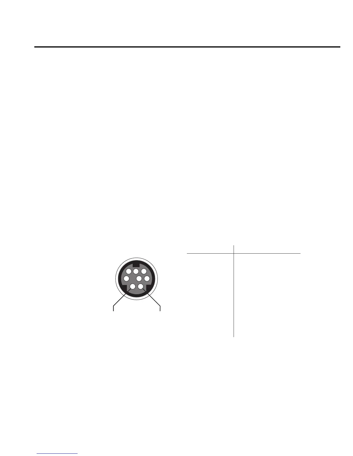
At the factory, line 1 is configured as VMC and line 2 as EXT TRIG. (Changing this
configuration is described in the Model 2010 Service Manual.) A connector pinout is shown in
Figure 3-3.
Rear Panel Pinout
1
2
34
5
6
7
8
Pin 2
External
Trigger
Input
Pin 1
Voltmeter
Complete
Output
Pin Number Description
1
2
3
4
5
6
7
8
Voltmeter Complete Output
External Trigger Input
No Connection *
Signal Ground
No Connection *
No Connection *
No Connection *
Signal Ground
* Either pin 3 or 5 may be configured as an output instead of pin 1.
Either pin 4 or 6 may be configured as an input instead of pin 2.
See the Model 2010 Service Manual for details.
gure
-
ear panel pinout
Measurement Options 3-11

 Loading...


