Connections
Assuming factory default conditions, the basic procedure is:
1. Connect test leads to the INPUT HI and LO terminals of the Model 2010. Either the front
or rear inputs can be used; place the INPUTS button in the appropriate position.
2. Select the FREQ or PERIOD function.
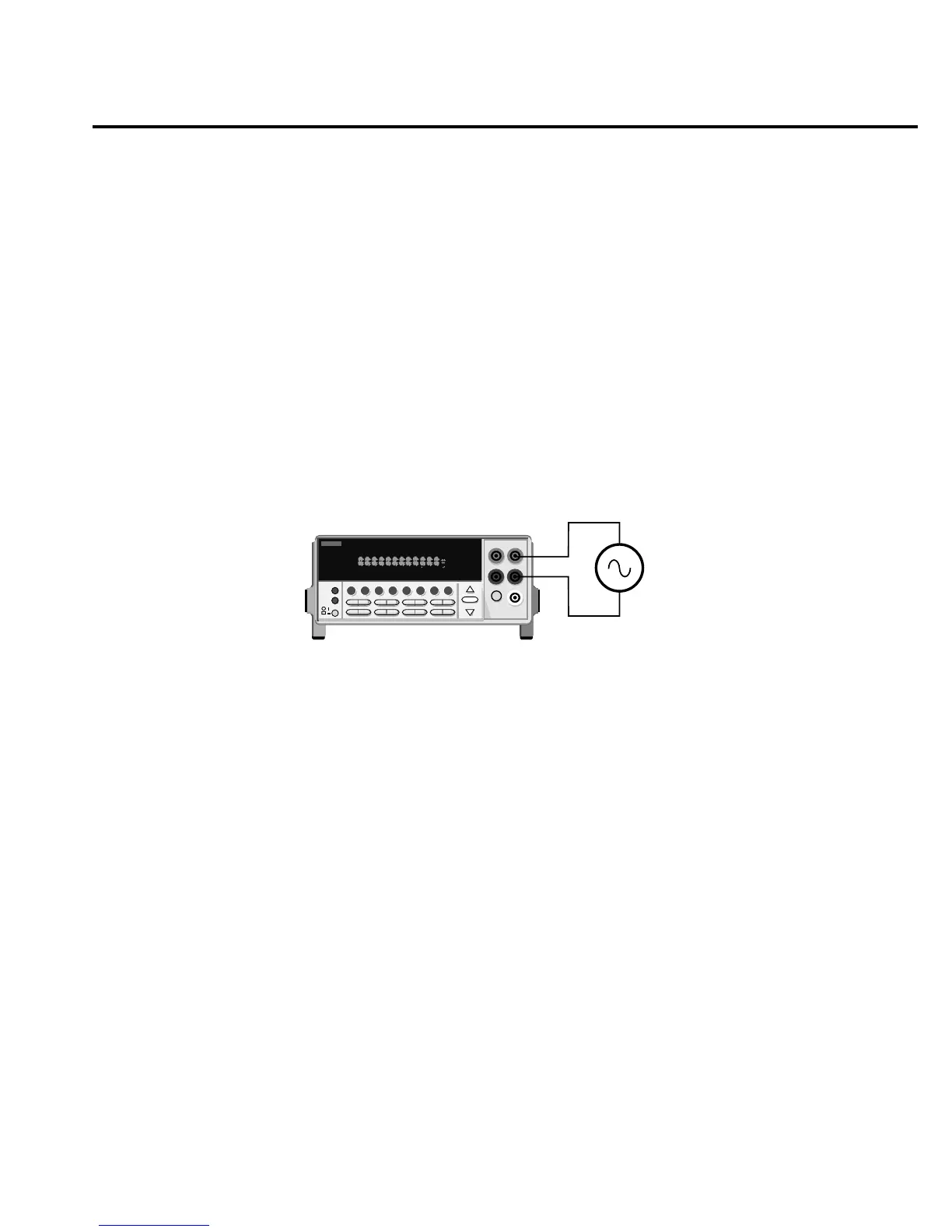
3. Connect test leads to the source as shown in Figure 2-8.
CAUTION Do not exceed 1000V peak between INPUT HI and INPUT LO or
instrument damage may occur.
4. Take a reading from the display.
See Section 3 for information on the configuration options for frequency and period
measurements.
2001 MULTIMETER
Model 2010
Caution: Maximum Input = 1000V peak, 8 x 10
7
V•Hz
AC Voltage
Source
Input Impedance = 1MΩ in parallel with <100pF
SHIFT
CH1REM
TALK
LSTN
SRQ
STATREL FILT
4W
BUFFER
MATH
REAR
SCAN
TIMER
STEP CH2 CH3 CH4 CH5 CH6 CH7 CH
8
CH9 CH1
0
HOLD TRIG FAST MED SLOW AUTO ERR
gure
-
requency and period
measurements
Basic Measurements 2-29

 Loading...


