Testing diodes
With a Model 2010, you can measure the forward voltage drop of general-purpose diodes and
the zener voltage of zener diodes. To test diodes, press SHIFT then , set the test current
range, connect the diode, and take a reading from the display.
NOTE Diode test has a non-selectable reading rate of MEDium (1 PLC).
Connections
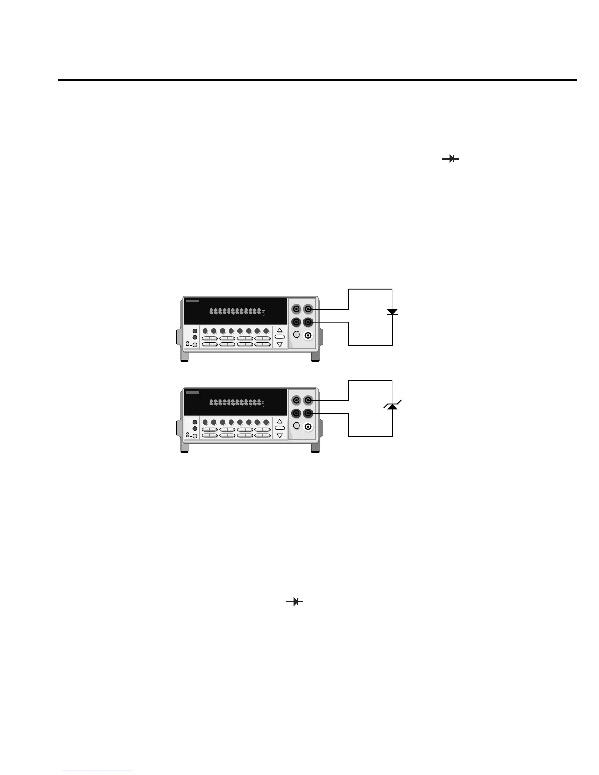
Connect the diode leads to the INPUT HI and INPUT LO terminals on the Model 2010. The
test current flows from the INPUT HI terminal as shown in Figure 2-11.
Range
You can set the test current range from the front panel. The choices are 1mA, 100µA, and
10µA. The factory test current setting is 1mA. To set the test current, perform the following
steps:
1. Press SHIFT and then .
2. Use the ▲ and ▼ keys to scroll through the three test current selections.
The diode test measures voltages up to 10V for the 1mA test current, 5V for 100µA, and 10V
for the 10µA range. If a reading is more than 10V, the Model 2010 displays the “OVERFLOW”
status message.
2001 MULTIMETER
Model 2010
General-Purpose
Diode
SHIFT
CH1REM
TALK
LSTN
SRQ
STATREL FILT
4W
BUFFER
MATH
REAR
SCAN
TIMER
STEP CH2 CH3 CH4 CH5 CH6 CH7 CH
8
CH9 CH1
0
HOLD TRIG FAST MED SLOW AUTO ERR
2001 MULTIMETER
Model 2010
Zener
Diode
SHIFT
CH1REM
TALK
LSTN
SRQ
STATREL FILT
4W
BUFFER
MATH
REAR
SCAN
TIMER
STEP CH2 CH3 CH4 CH5 CH6 CH7 CH
8
CH9 CH1
0
HOLD TRIG FAST MED SLOW AUTO ERR
Note: Source current flows from the
INPUT HI to INPUT LO terminals.
gure
-
iode testing
Basic Measurements 2-37

 Loading...


