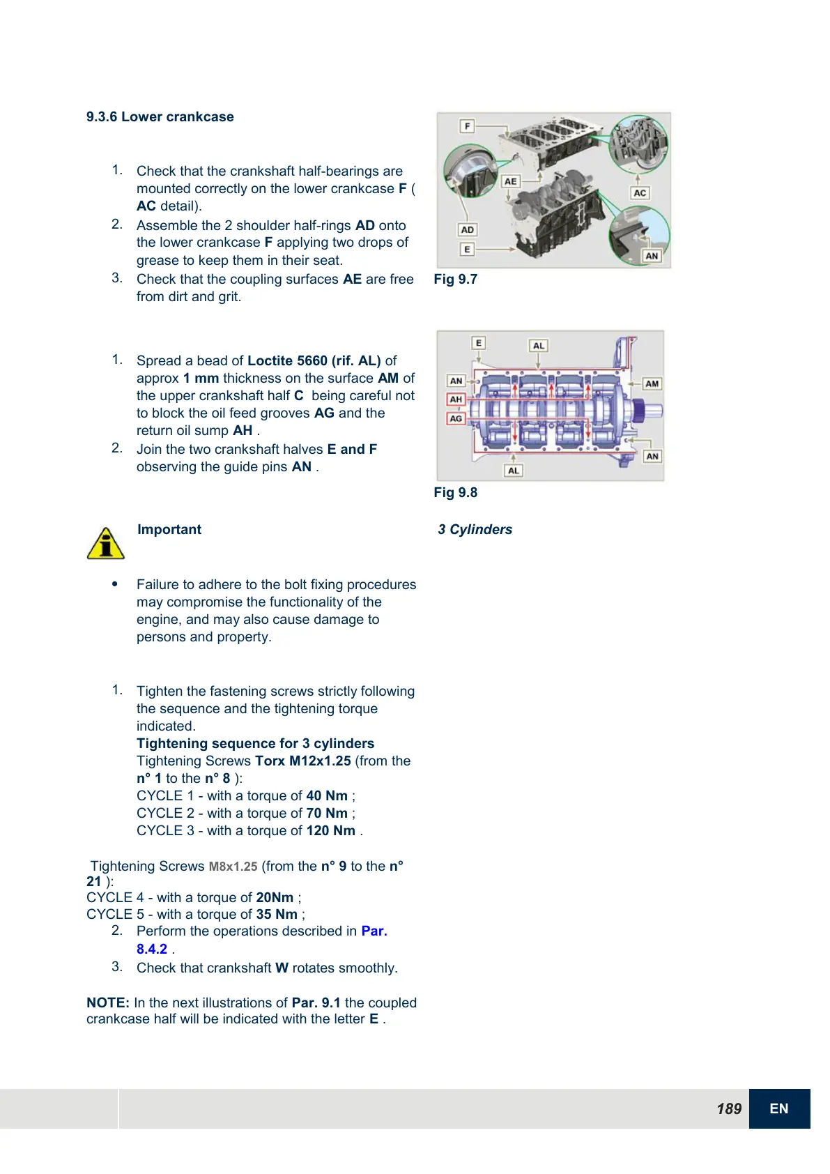
9.3.6 Lower crankcase
1.
Check that the crankshaft half-bearings are
mounted correctly on the lower crankcase F (
AC detail).
2.
Assemble the 2 shoulder half-rings AD onto
the lower crankcase F applying two drops of
grease to keep them in their seat.
3.
Check that the coupling surfaces AE are free
from dirt and grit.
1.
Spread a bead of Loctite 5660 (rif. AL) of
approx 1 mm thickness on the surface AM of
the upper crankshaft half C being careful not
to block the oil feed grooves AG and the
return oil sump AH .
2.
Join the two crankshaft halves E and F
observing the guide pins AN .
Important
Failure to adhere to the bolt fixing procedures
may compromise the functionality of the
engine, and may also cause damage to
persons and property.
1.
Tighten the fastening screws strictly following
the sequence and the tightening torque
indicated.
Tightening sequence for 3 cylinders
Tightening Screws Torx M12x1.25 (from the
n° 1 to the n° 8 ):
CYCLE 1 - with a torque of 40 Nm ;
CYCLE 2 - with a torque of 70 Nm ;
CYCLE 3 - with a torque of 120 Nm .
Tightening Screws M8x1.25 (from the n° 9 to the n°
21 ):
CYCLE 4 - with a torque of 20Nm ;
CYCLE 5 - with a torque of 35 Nm ;
2.
Perform the operations described in Par.
8.4.2 .
3.
Check that crankshaft W rotates smoothly.
NOTE: In the next illustrations of Par. 9.1 the coupled
crankcase half will be indicated with the letter E .

 Loading...


