DETAILED CONTROLS AND GAUGES OPERATION
3-146
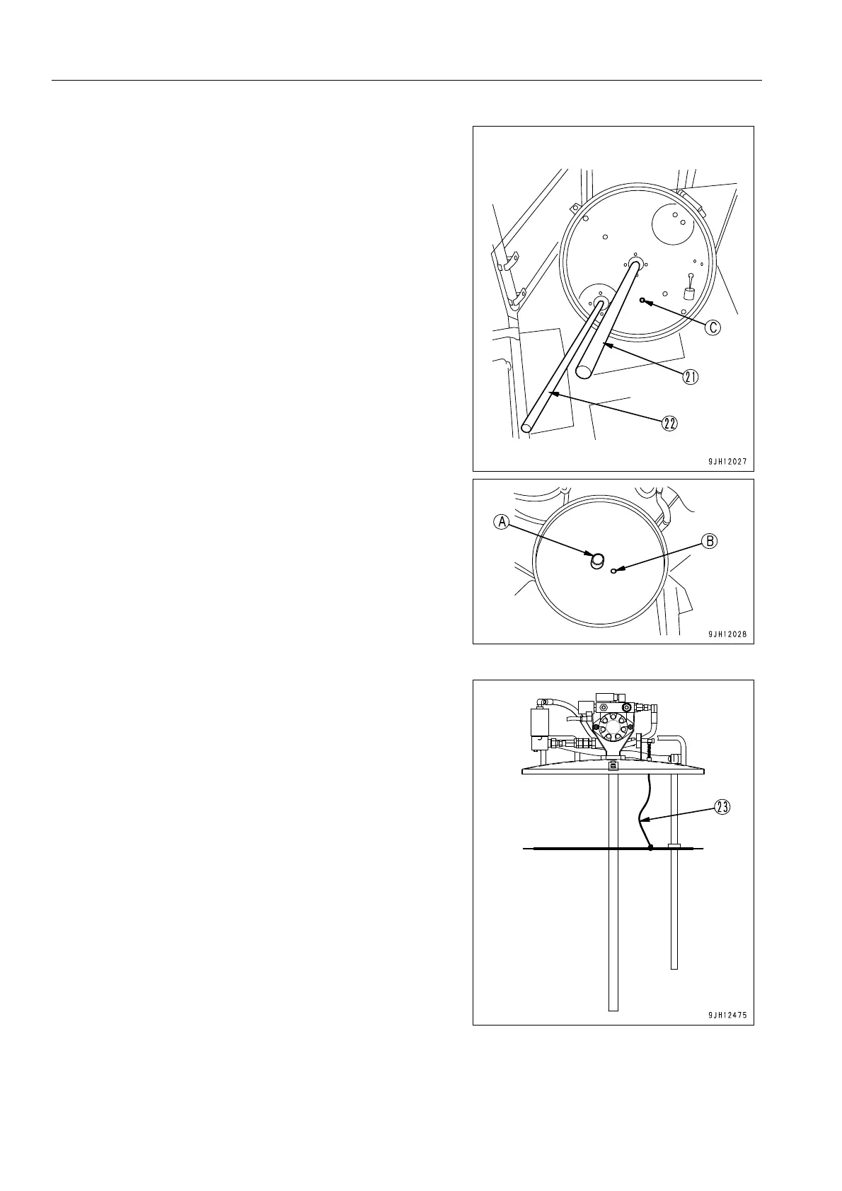
10. Lift up grease can cover (16), align shaft (21) and shaft
(22) with follower plate holes (A) and (B), then insert the
shafts.
11. Insert wire (23) of the grease level sensor through hole (C)
in grease can cover (16).
12. Be careful not to drop wire (23) into the grease can when
inserting it. Insert grease can cover (16) until it is in tight
contact with the grease can itself.
13. Set the grease can on the machine, then set the grease
can cover (16) in the reverse order to Steps 1 - 5.
 Loading...