X75HD/X75SD Installation and Operation Manual 55
Chapter 3: Module and Back Panel Descriptions
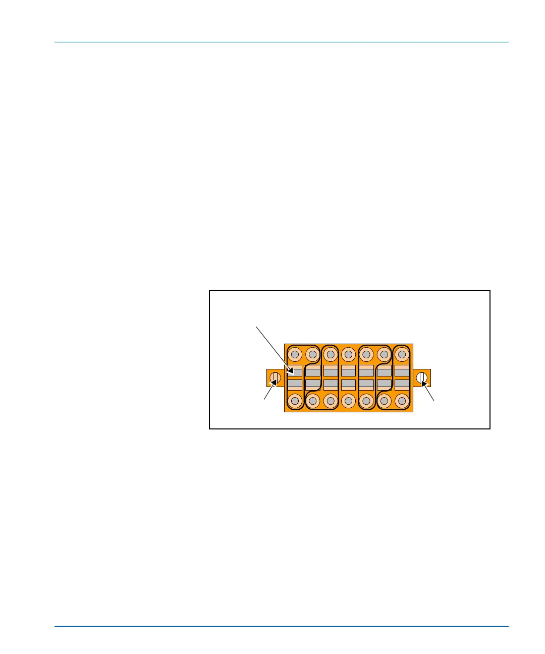
Installing Audio Receptacles
To make analog audio input and output connections, you need to
properly connect stripped wires for each audio channel to the provided
audio receptacle. Once done, install the wired receptacle to the back
panel audio input and output connectors. Follow these steps:
1. Insert a small, flathead screw driver into a rectangular hole of the
audio receptacle.
The corresponding round wire hole will open either directly above
or directly below the screwdriver (see Figure 3-3).
2. Heeding the positive (+), negative (-), and ground (GND) markings
on the back panel, place an appropriate stripped audio wire into the
open hole.
The top row of wire connection holes alternate between positive
and ground. The bottom row of wire connection holes alternate
between negative and ground. See Figure 3-3.
Figure 3-3. Installing Analog Audio Receptacles
3. Remove the screwdriver to lock the wire into place.
4. Repeat for other wire connections.
5. Once all wiring in completed, plug the receptacle into the analog
audio input ports (each labelled CH1 CH2 CH3 CH4), and then
secure the receptacle into place with the attached connector screws.
+ G + G + G +
- G - G - G -
CH1 CH2 CH3 CH4
+
-
GND GND GND
+
-
+
-
+
-
Connector
screw
Rectangular slot
Insert a flathead screwdriver into a rectangular slot to
open a corresponding round connection point (above or
below)
Connector
screw