• Do not modify the interior workings of the inverter. Doing so will void the warranty.
• The inverter is designed for 3-phase motor operation. Do not use the inverter to operate a single
phase motor.
• Do not place heavy objects on top of electric cables. Doing so may damage the cable and
result in an electric shock.
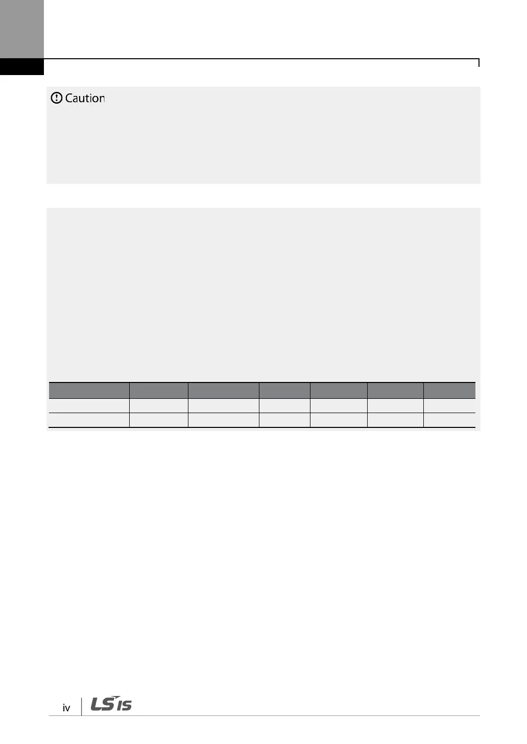
Maximum allowed prospective short-circuit current at the input power connection is defined in IEC
60439-1 as 100 kA. Depending on the selected MCCB, the LSLV-S100 Series is suitable for use in circuits
capable of delivering a maximum of 100 kA RMS symmetrical amperes at the drive's maximum rated
voltage. The following table shows the recommended MCCB for RMS symmetrical amperes.
Remarque
Le courant maximum de court-circuit présumé autorisé au connecteur d’alimentation électrique est
défini dans la norme IEC 60439-1 comme égal à 100 kA. Selon le MCCB sélectionné, la série LSLV-S100
peut être utilisée sur des circuits pouvant fournir un courant RMS symétrique de 100 kA maximum en
ampères à la tension nominale maximale du variateur. Le tableau suivant indique le MCCB
recommandé selon le courant RMS symétrique en ampères.
Working Voltage
UTE100(E/N)
UTS150(N/H/L)
ABS33c
ABS53c
ABS63c
ABS103c
480V(50/60Hz) 25/35 kA 35/65/100 kA 7.5 kA 10 kA 10 kA 26 kA

 Loading...


