Section 4 – OUTRIGGER SETTING Mini-Crawler Crane M A E D A
4-48 1/2019 MC405C-3
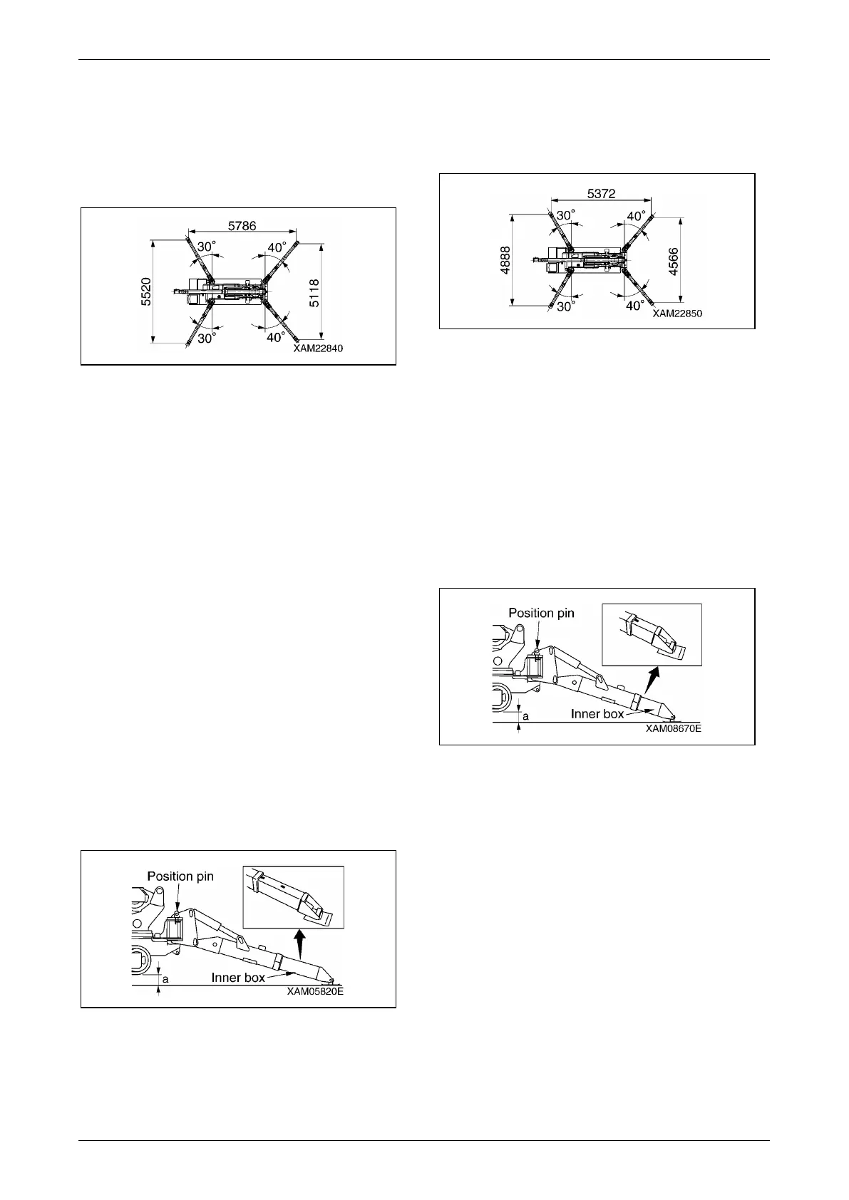
Outrigger Extension Modes
Outrigger Maximum Extension
The figure represents the condition "When the
crane is used with the outriggers extended at the
maximum" in the rated total load chart.
Fig. 4-118
Ensure that all the lamps, other than the boom
stowing lamp on the outrigger monitor, are on.
If the inner box is retracted even if only slightly,
crane operation should proceed with respect to
the values specified in the rated total load chart
corresponding to "When the crane is used with
the outriggers extended at the
minimum/medium".
For more information on proper setting of the
outriggers, see "OUTRIGGER SETTING" on
page 4-42.
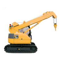
NOTICE: Outrigger maximum extension is
defined as that:
1. The outrigger is set at the positioning pin
position (40° front, 30° back).
2. The inner box of all the outriggers is
extended fully.
3. All the outriggers are placed on a level
surface.
4. Approx. 50mm is assured for clearance "a"
(between the outrigger bottom and crawler
bottom) in the figure.
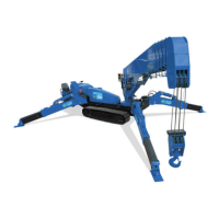
Fig. 4-119
Outrigger Medium Extension
The figure shown represents the condition "When
the crane is used with the outriggers extended at
the medium" in the rated total load chart.
Fig. 4-120
NOTICE: Outrigger medium extension is defined
as that:
1. The outrigger is set at the positioning pin
position (40° front, 30° back).
2. The inner box of all the outriggers is
extended at the medium.
3. All the outriggers are placed on a level
surface.
4. Approx. 50mm is assured for clearance "a"
(between the outrigger bottom and crawler
bottom) in the figure.
Fig. 4-121
NOTICE: If even a group of outriggers is
retracted to a medium point, all the outriggers are
deemed to be extended at the medium.