Section 4 – REMOTE CONTROL SYSTEM COMPONENTS Mini-Crawler Crane M A E D A
4-92 1/2019 MC405C-3
REMOTE CONTROL SYSTEM COMPONENTS
Transmitter
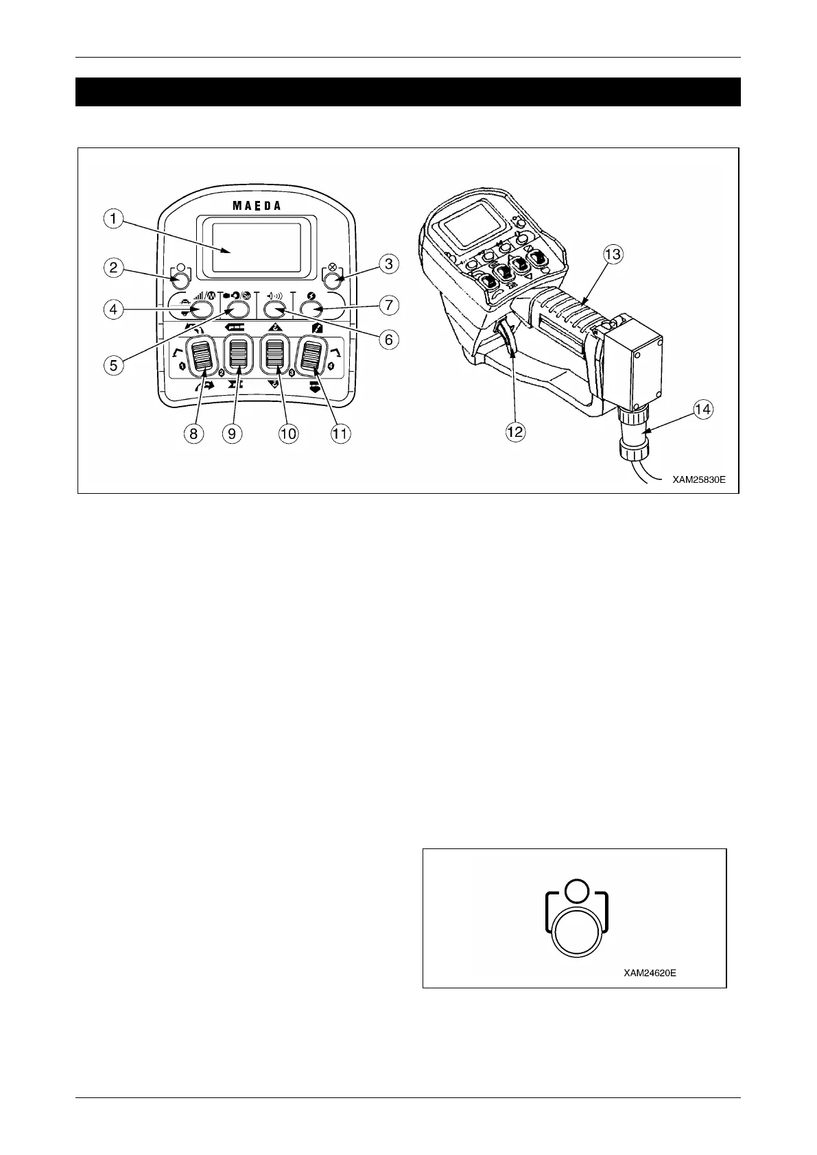
Fig. 4-234
1 - LCD Screen
2 - Start/Reset Button
3 - Stop/EMO Button
4 - Speed/Mode Button
5 - Hook Stow/Setting Button
6 - Horn Button
7 - Power Switch
8 - Slewing/No.1 Outrigger Operation Lever
9 - Boom Telescoping/No.2 Outrigger
Operation Lever
10 - Hook Raising and Lowering/No.3 Outrigger
Operation Lever
11 - Boom derricking/No.4 Outrigger Operation
Lever
12 - Accelerator Lever
13 - Grip
14 - Connection Cable
LCD Screen
The LCD screen displays the status of the
Transmitter in operation, the established values
for each mode, or error messages by symbols,
comments or signs.
Start/Reset Button
This button has two usages as below:
• To push this button starts the engine.
• This button resets the "Emergency Stop" and
"Abnormal Signal Detect" conditions.
Fig. 4-235