Mini-Crawler Crane M A E D A Section 4 – REMOTE CONTROL SYSTEM COMPONENTS
1/2019 MC405C-3 4-99
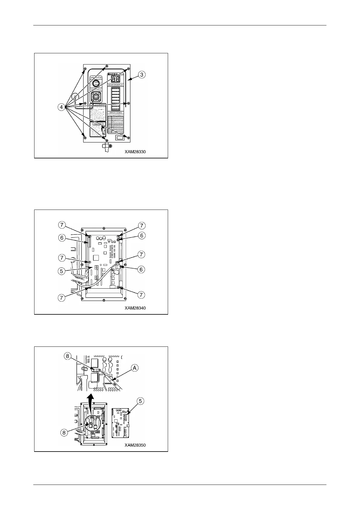
2. Unfasten eight of screws (4) and take away
the cover of the Receiver (3).
Fig. 4-255
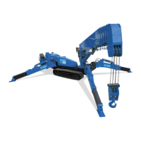
3. Extract three of connectors (6) in the first
PCB (5).
4. Unfasten six of screws (7) and remove the
first PCB (5).
Fig. 4-256
5. With a jeweler’s driver (A) to pull out the fuse
(8) from its clips, then examine it.
Fig. 4-257
6. Insert a new fuse or the examined fuse to
where the one was.
Insertion of a Fuse
After the fuse is examined or replaced, restore
the Receiver in the reverse practice of the
removal.
CAUTION:
• When the three connectors (6) of the first
PCB (5) is inserted again, secure them and
avoid any loose conditions.
• Care should be exercised so that the cover
(3) of the Receiver will not catch wires when
it is attached back.
[Fuse class]
Type: Grass tube fuse
Rating: 15A