Section 5 – GENERAL MACHINE MAINTENANCE Mini-Crawler Crane M A E D A
5-68 1/2019 MC405C-3
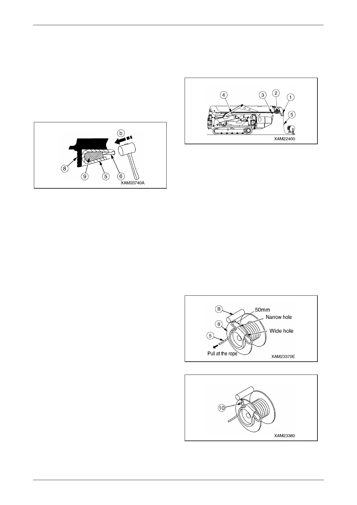
8. With the wire rope winded up from the winch
drum, detach the end of the wire rope (5)
from the winch drum (8) by following the
procedure provided below.
(1) Bring a 4 to 6mm round bar (6) into
contact with the rope wedge (9).
(2) Remove the rope wedge (9), lightly
tapping the round bar (6) with a hammer
in the direction indicated by the arrow
(b).
Fig. 5-163
9. Wind up the remaining wire rope (5)
completely.
Removal of the winch wire rope is completed.
Winch Wire Rope - Installation
WARNING! Be sure to attach the rope wedge
properly to secure the wire rope. Potential
serious accident may occur due to
detachment of the wire rope during crane
operation if disregarded.
CAUTION:
• Avoid irregular winding of the wire rope in
the winch drum.
• Always hoist an object (2.9 to 4.9KN {300 to
500kg}) with the boom extended and raised
fully immediately after attaching a new rope.
Repeat raising and lowering the hook
several times until the new rope conforms.
• The wire rope is coiled. Exercise caution not
to form a kink in the rope when winding it
up.
Be sure to unrope by rotating the rope to
pull it out of the winch drum.
Use the following procedure to attach the wire
rope.
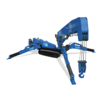
1. With the end of the wire rope held, draw the
wire rope (5) through the weight of the over
winding detector, load sheave (1) at the
boom end, wire guide (2) of No.2, 3, and 4
boom, snap sheave (3), and idler sheave (4).
Fig. 5-164
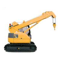
2. Draw the wire rope (5) through the
attachment hole of the winch drum (8).
Secure the wire rope (5) to the winch drum
(8), following the procedure provided below.
(1) Draw the wire rope (5) through the
winch drum (8) with the rope loose.
(2) The rope wedge (9) should be in
position (a). Pass the wire rope (5)
around the rope wedge and yank at the
rope in the direction indicated by the
arrow.
Let the wire rope (5) protrude
approximately 50 mm out of the narrow
hole in the winch drum (8), then fix the
end of the wire rope (5) with the plate
(10).
Fig. 5-165
Fig. 5-166