Section 5 – GENERAL MACHINE MAINTENANCE Mini-Crawler Crane M A E D A
5-72 1/2019 MC405C-3
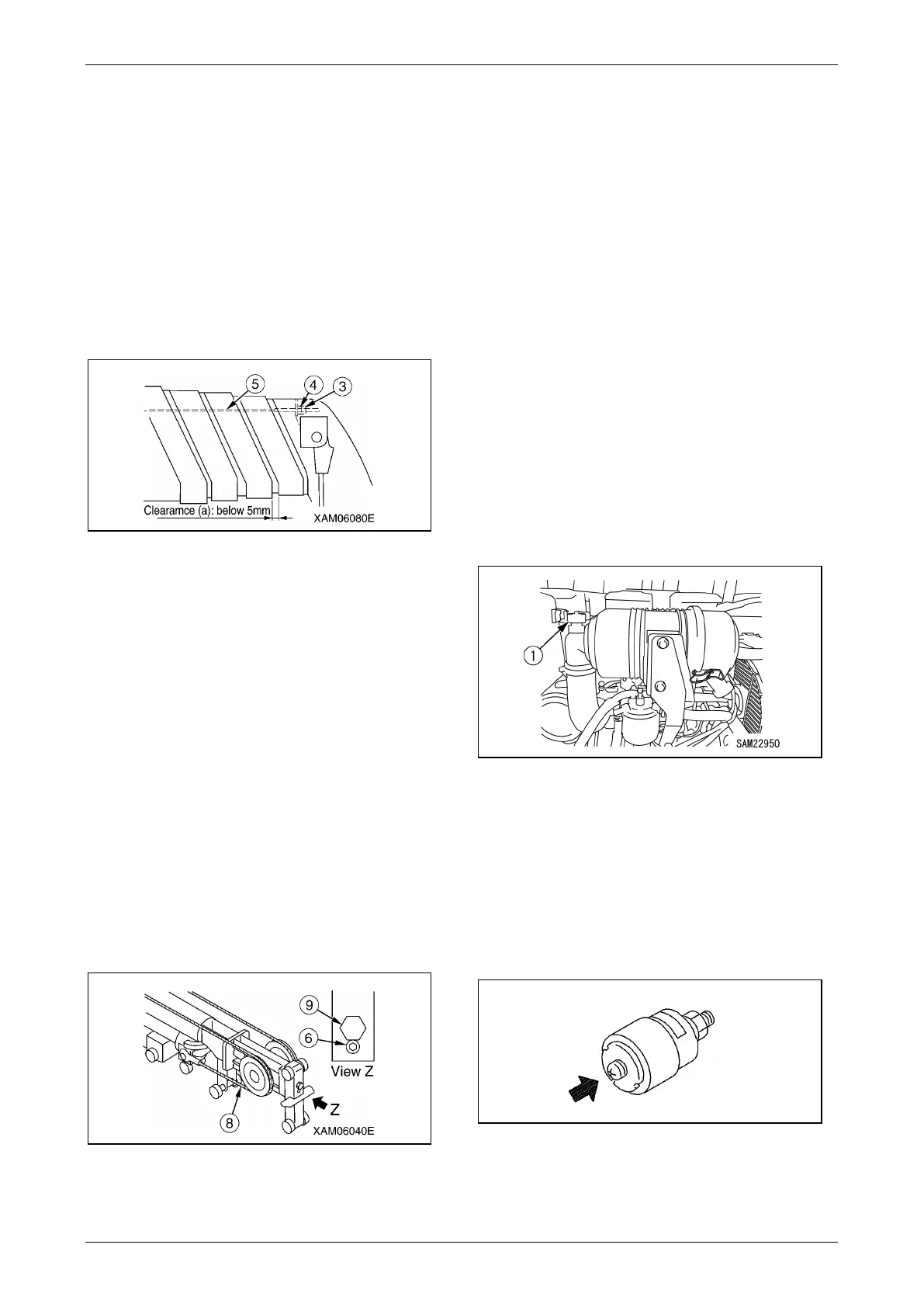
4. Adjustment of boom No.5 retracting wire
rope (5)
(1) With the lock nut (3) loose, turn the
adjusting nut (4) in the direction that the
retracting wire rope (5) becomes tight
(clockwise (right)) to provide laterally
even tightening until clearance (a) is
bridged.
(2) If the retracting wire rope remains
sagging or 5-mm or more clearance
remains present after performing steps
1 and 2, readjustment is required.
Fig. 5-179
5. Adjustment of boom No.5 extending wire
rope (8)
(1) Remove the lock bolt (6). Turn the
adjusting bolt (9) in the direction that the
extending wire rope (8) of boom No.5
becomes tight (clockwise (right)) to
provide tightening to the verge of the
extension of boom No.5.
(2) Provide retightening to both adjusting
nuts (4) of the boom No.5 retracting wire
rope (5) two turns each.
(3) Secure the adjusting nuts (4) of the
boom No.5 retracting wire rope (5) with
the lock nut (3).
(4) Provide retightening to both adjusting
bolt (9) of the boom No.5 extending wire
rope (8), and secure it with the lock bolt
(6).
Fig. 5-180
6. Install the cover (2) to the boom end with the
three mounting bolts (1) upon completion of
adjustment.
Inspection, Cleaning and
Replacement of Air Cleaner
WARNING!
• Conducting inspection/cleaning
maintenance while the engine is running
may allow the entry of rubbish into the
engine and damage the engine. Conduct
after stopping the engine.
• When using compressed air, rubbish can fly
in all directions and may cause personal
injuries. Wear goggles, dust mask and other
protective equipment.
Inspection
1. Remove the machinery cover as described
in "Removing Machinery Cover" on page 5-
18.
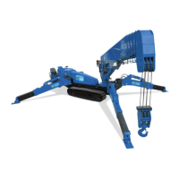
Fig. 5-181
2. Inspect the dust indicator (1) on the air
cleaner to check that the red piston is not
visible in the transparent section.
3. If the red piston is visible, clean or replace
the element immediately.
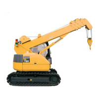
4. After inspecting, cleaning or replacing, press
the knob on the dust indicator (1) to return
the red piston to its original position.
Fig. 5-182
5. Reattach the machinery cover as described
in "Installing Machinery Cover" on page 5-
18.