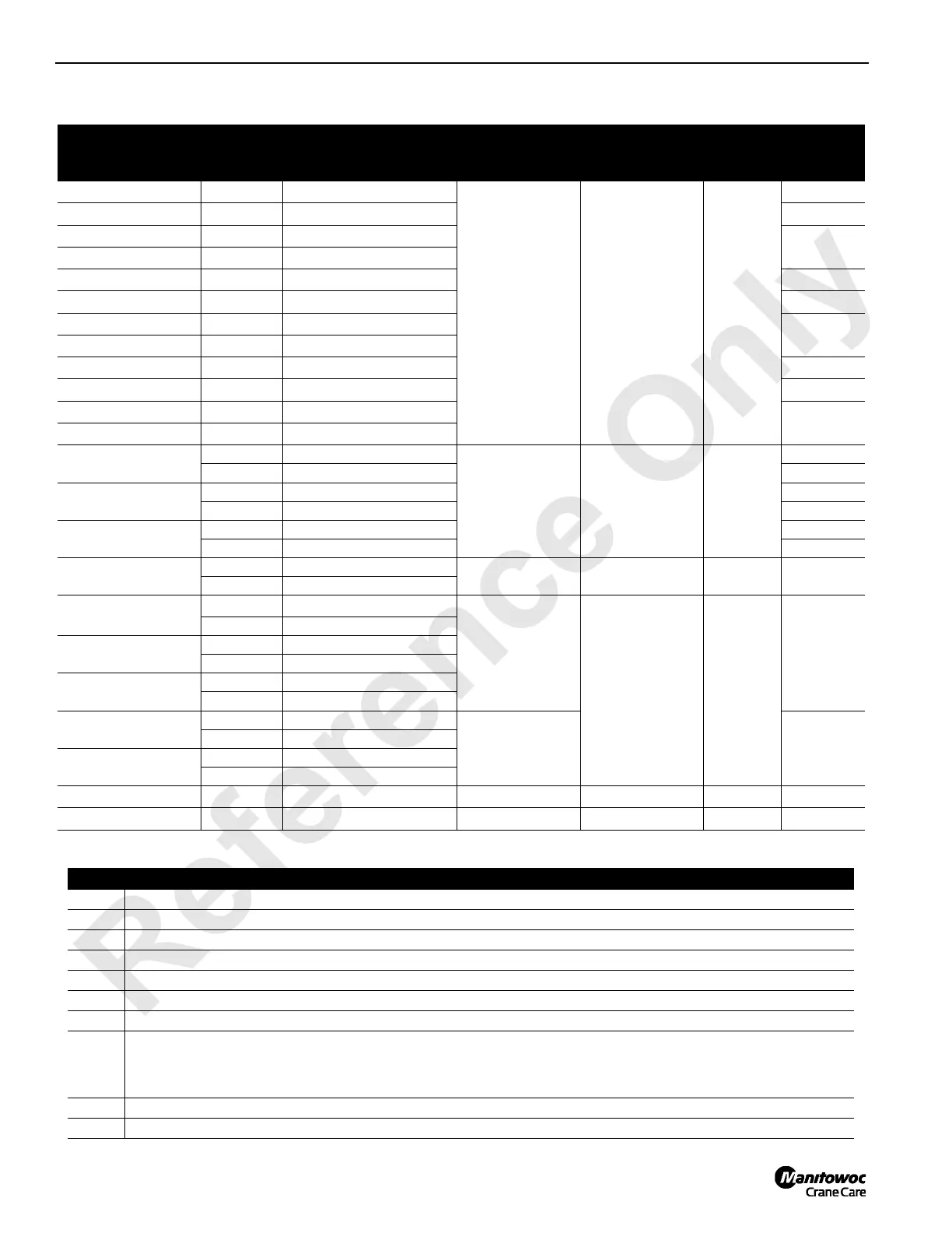
Function Direction
Pump-Motor Port
Connections
System
Pressure 1
1
psi (bar)
System
Pressure 2
2
psi (bar)
Charge
Pressure
Speed
3
rpm
Drum 1
9
Low Speed
Lower Pump B to Motor B
2,900 (200) Lower
6,090 (420) Hoist
N/A 350 (24)
40-48
Drum 1
9
Low Speed
Hoist Pump A to Motor A
45-50
Drum 1
9
High Speed
Lower Pump B to Motor B
50-56
Drum 1
9
High Speed
Hoist Pump A to Motor A
Drum 2
4
Low Speed
Lower Pump B to Motor B
40-48
Drum 2
4
Low Speed
Hoist Pump A to Motor A
45-50
Drum 2
4
High Speed
Lower Pump B to Motor B
50-56
Drum 2
4
High Speed
Hoist Pump A to Motor A
Drum 3
4
Low Speed
Lower Pump B to Motor B
40-48
Drum 3
4
Low Speed
Hoist Pump A to Motor A
45-50
Drum 3
4
High Speed
Lower Pump B to Motor B
50-56
Drum 3
4
High Speed
Hoist Pump A to Motor A
Boom Hoist
Drum 4
5
Lower Pump B to Motor A
2,900 (200) Lower
6,090 (420) Hoist
N/A 350 (24)
14-17
Hoist Pump A to Motor B 16-18
Luffing Jib Hoist
Drum 5
5
Lower Pump B to Motor B 34-40
Hoist Pump A to Motor A 38-42
MAX-ER Main Hoist
Drum 9
6
Lower Pump B to Motor A 38-46
Hoist Pump A to Motor B 43-48
Rigging Winch
Haul In N/A
3,000 (204) N/A N/A 85-90
Pay Out N/A
Swing Single Drive
Left
Pump A
to Motor A
6,090 (420)
Right or Left
N/A 350 (24)
1.1-1.5
Right Pump B to Motor B
Swing Dual Drive
7
Left Pump A to Motors A
Right Pump B to Motors B
Swing Dual Drive High
Speed
7
Left Pump A to Motors B
Right Pump B to Motors A
Left Side Travel
6
Forward Pump B to Motor A
6,090 (420)
Forward or Reverse
8 to 9
at Tumbler
Reverse Pump A to Motor B
Right Side Travel
6
Forward Pump B to Motor A
Reverse Pump A to Motor B
Accessory Pumps
8
N/A Open Loop to Tank
N/A 0 to 3,500 (0 to 241) N/A N/A
Fan Pump
10
N/A Open Loop to Tank
3,250 (224)
Notes
1 Controlled by multi-function valves in each pump.
2 Controlled by crane’s programmable controller.
3 Speeds based on engine at high idle, no load (no rope on drums), and handles moved fully forward or back.
4 Same pump is used for split rear drum 2 or 3. Active drum is selected by first handle moved.
5 Pump used for Boom Hoist 4 or Luffing Jib Hoist 5. Active drum will not hoist until alternate drum is parked.
6 Pumps used for MAX-ER Main Hoist Drum 9 or travel left side and right side.
7 Dual swing standard with MAX-ER 2000 prep; high speed swing motors optional for clam operation.
8
Accessory pumps are the source of hydraulic pressure for accessory system and high pressure accessory components. Items
include swing and travel brakes, Boom hinge pin cylinders, rotating bed jacking cylinders, front and rear adapter frame pin cylinders,
mast pins and raising cylinders, cab tilt cylinder, rigging winch, crawler pin cylinders, and MAX-ER 2000. Computer controls pump
pressure depending on accessory selected.
9 Optional Front Drum 1 is not present in MAX-ER configuration.
10 Fixed displacement fan pump also supplies low pressure to MAX-ER Drum 9 accessory.
 Loading...


