BOOM 2250 SERVICE/MAINTENANCE MANUAL
4-8
Published 11-06-15, Control # 040-13
The sending unit for the boom and for the luffing jib are
identical in appearance. The two units are different,
however, and must not be interchanged.
The sending unit for the boom has a 120° potentiometer. This
potentiometer is labeled CP17-0693-1.
The sending unit for the luffing jib has a 178
° potentiometer.
This potentiometer is labeled CP17-0694-1.
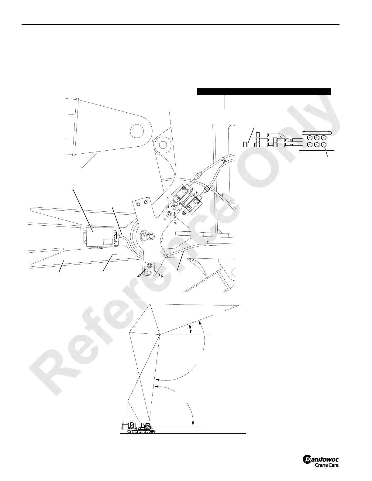
FIGURE 4-6
Item Description
A Shorting Plug for Luffing Jib Angle
B Electric Cord to Luffing Angle Sending Unit
Bottom View of Junction Box
on Left Outboard Side of
Boom Top
Layout luffing jib shown.
Fold-under luffing jib similar.
Angle Sending Unit
• Left Outboard Side of Luffing Jib Butt
• Right Inboard Side of Boom Butt
Electric
Cord
Luffing
Jib Butt
Protective
Cap
B
B
A
A1049
FIGURE 4-7
Boom and Jib Angle Identification
A528
C
L
C
L
Boom
Boom to Luffing
Jib Angle
Boom Angle
Horizontal
Horizontal
Luffing Jib
Luffing Jib
Angle
 Loading...


