Manitowoc Published 11-06-15, Control # 040-13 4-11
2250 SERVICE/MAINTENANCE MANUAL BOOM
5. Scroll to desired angle on digital display in operator’s
cab.
6. Angle shown on digital display must match angle
recorded in step 4
plus or minus one degree.
7. If necessary, loosen mounting screws and rotate
sending unit in mounting slots until reading on digital
display matches angle on protractor-level.
8. Securely tighten mounting screws to lock adjustment.
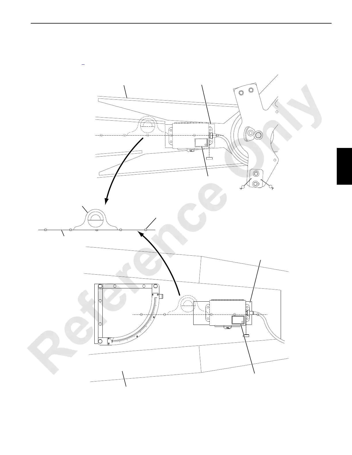
FIGURE 4-10
A1049
Jib Butt
Support
Protractor
Level
Scribed
Line
Center of Outboard Plates on Boom and
Jib Butts are Punch Marked at Factory.
Scribe a Line Through Punch Marks.
Angle Sending Unit
on Luffing Jib Butt
Support
Angle Sending Unit
on Boom Butt
Boom Butt
 Loading...


