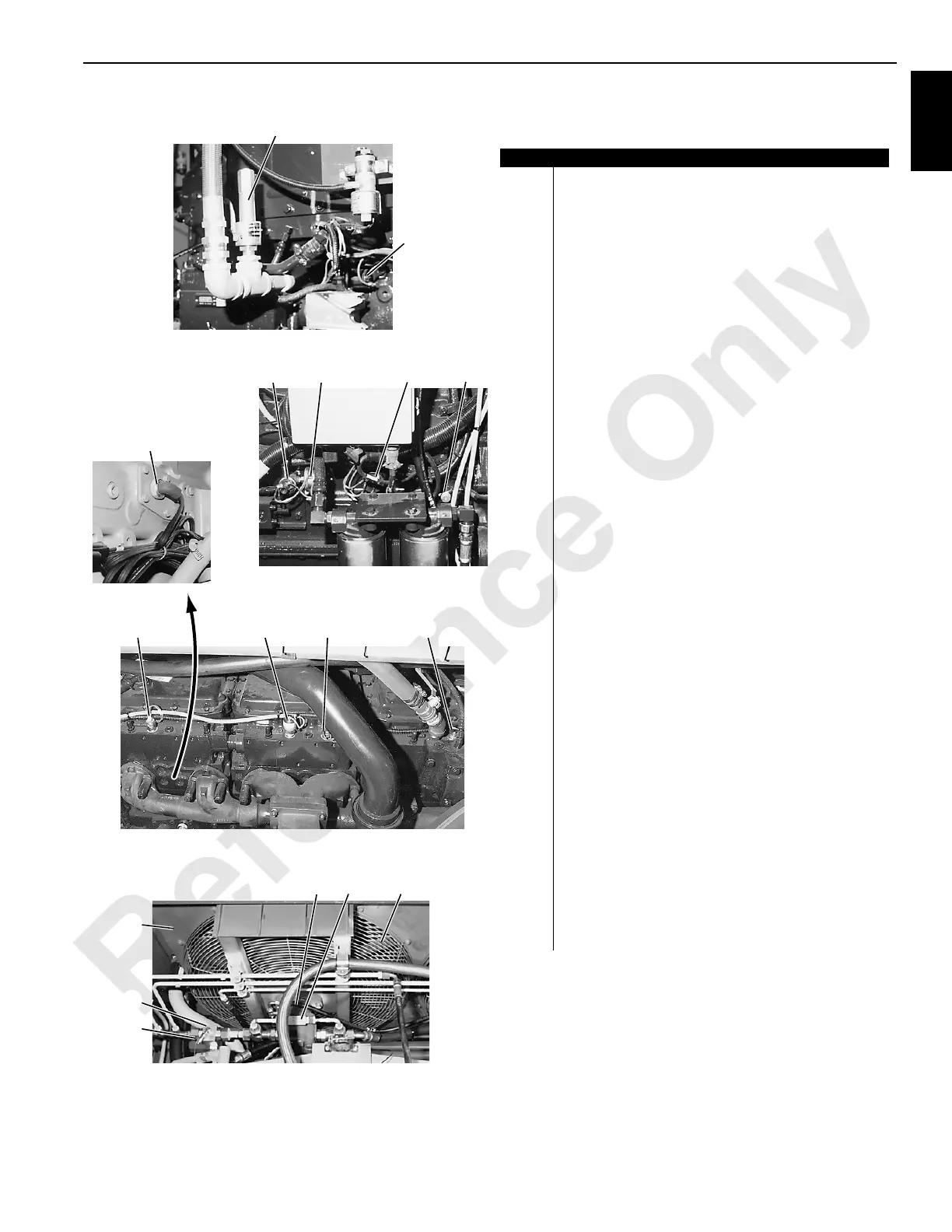
Item Description
1 Diagnostic Gauge Coupler (typical each sender)
2 Right Travel Pressure Sender
3Spares
4 Boom Hoist Pressure Sender
5 Load Drum System Pressure Sender
6 Load Drum Charge Pressure Sender
7 Swing Right “B” Pressure Sender
8 Swing Left “A” Pressure Sender
9 Left Travel Pressure Sender
10 Pump Control Junction Box
11 Suction Line Pressure Sender Junction Box
12 Hydraulic Control Junction Box
13 Leveling Sensor Junction Box
14 Engine Hour Meter
15 Engine Junction Box
16 Air Conditioner Compressor
17 Air System Compressor
18 Ether Start Solenoid Valve
19 Ether Start Tank
20 Electronic Fuel Control Junction Box
21 Engine Fly Wheel
22 Engine Speed Sender (Production before Tier 1 engine)
23 Pump Drive
24 Engine Starter
25 Alternator
26 Air System Safety Valve
27 Electronic Fuel Control Actuator
28 Engine Oil Pressure Switch
29 Engine Oil Pressure Sender
30 Engine Oil Pressure Switch (disables hydraulic
disconnect if engine is running)
31 Ground Stud
32 Engine Block Heater (1500W 120V with extension cord)
33 Ether Start Disable Switch (Past Production Only)
34 Fan Switch (with cold weather package only)
35 Engine Coolant Temperature Switch
36 Engine Coolant Temperature Switch Sender
37 Diagnostic Gauge Coupler
38 Engine Coolant Radiator (top portion)
Hydraulic Oil Cooler (bottom portion)
39 Fan Relief Valve
40 Fan Motor
41 Fan Anti-Cavitation Check Valve
42 Radiator and Oil Cooler Fan
View from Front
of Crane Above Engine
(typical 2 places)
26
View D
P934
P933
P587
P860
View E
27
31
302928
32
View F
33 34 35 36
37
38
39
40 41 42
P935
FIGURE 1-8 continued
 Loading...


