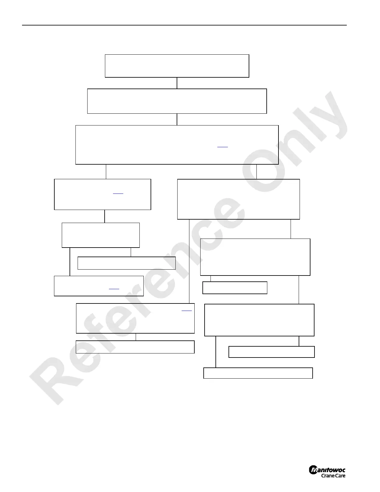
CHECKS
Check for 3,500 psi pressure at auxiliary system disable valve while enabling
any upper valve assembly components. (See Te st
25.)
PROBLEM 32
Upper and lower valve cylinders are not operating.
POSSIBLE CAUSES
Faulty relief valve, auxiliary system disable valve or switch or wiring. Fan
circuit component failure; Pump is bad; Wiring problem.
3,500 psi or less
3,500 psi or more
300 psi or less
Check pressure at pilot/brake pressure
relief valve. (See Tes t
24.)
Are fan impellers turning?
Yes No
Adjust or replace pilot/brake pressure
relief valve. (See Te st
24.)
Check fan circuit for component failure.
Adjust auxiliary system working pressure. (See Tes t
25.) Are cylinders operating correctly?
No
Repair or replace auxiliary system disable valve.
Enable any upper valve assembly component in
both directions and check that voltage is present
at auxiliary system disable valve.
Voltage
No Voltage
Yes
No
Does diagnostic display screen. D1 (bank 3)
change by 4 when enabling any auxiliary
system valve?
Repair or replace wiring.
Yes
No
Is crane set-up mode selected and confirmed at
operator display?
Replace fuse F13 or power switch or wiring.
Select and confirm set-up mode.
 Loading...


