Operating elements for crane operation
9.2 Short description of the operating elements
9 - 134 3 302 690 en Operating manual
GMK4100L-1
23.11.2017
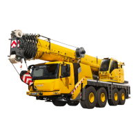
Maximum permissible working radius display
Shows the maximum permissible working
radius (5) for each slewing range.
Current working radius display
Current slewing angle display
Current position display
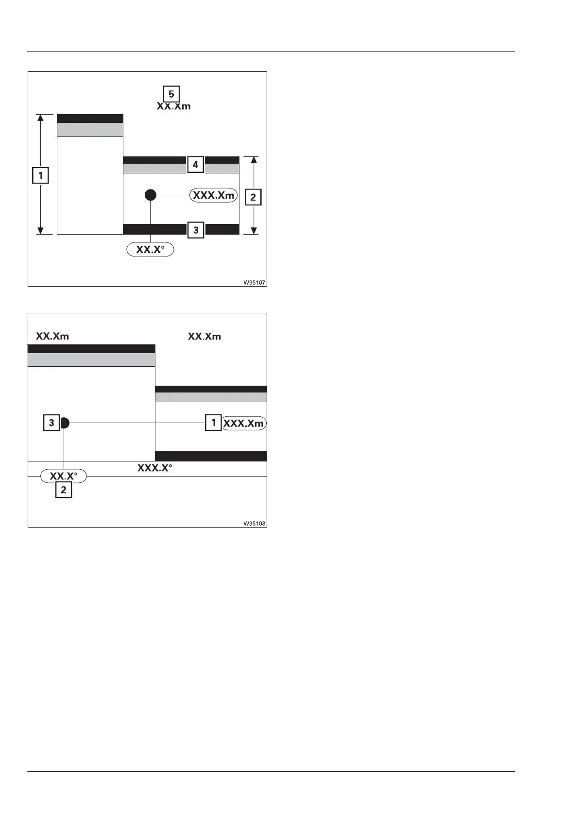
– When slewing
The display (3) remains at the current position. The chart moves a corre-
sponding distance to the right or left.
– When telescoping or derricking
The diagram remains at the current position. The display (3) moves a
corresponding distance up or down.
à Slewing range type Standard, p. 11 - 53
à Slewing range type MAXbase, p. 11 - 55
1 Display area – always corresponds to the
largest maximum working radius (5)
2 Maximum permissible working radius in
the corresponding slewing range with the
currently lifted load
3 White – limit region for minimum permis-
sible working radius (display only with
active limitation)
4 Red/yellow – limit region for maximum
permissible working radius
1 Display occurs in the same manner as in
the
Monitoring menu; à p. 11 - 49.
2 Display occurs in the same manner as in
the
Monitoring menu; à p. 11 - 50.
3 Shows the current position of the boom
head in the slewing range and working
radius range.

 Loading...