CSP−900RMM−2MD Helicopters, Inc.
Rotorcraft Maintenance Manual
Page 401
Original
78-00-00
ENGINE EXHAUST
REMOVAL / INSTALLATION
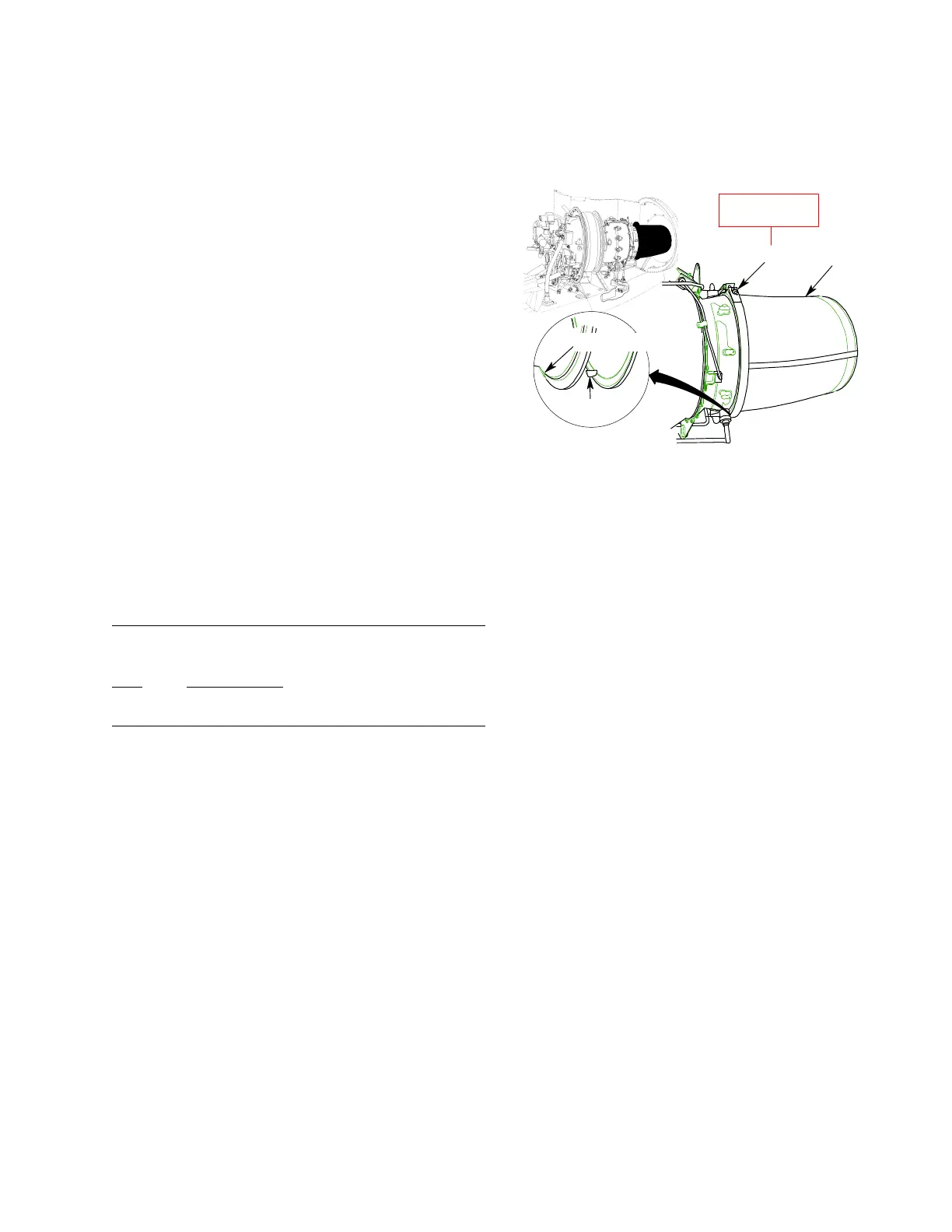
1. Primary Exhaust Nozzle Assembly
A. Primary Exhaust Nozzle Assembly
Removal
(Ref. Figure 401)
NOTE: This task is typical for left or right hand
primary exhaust nozzle.
(1). Open engine cowling assembly L260 or
R260 (Ref. Section 06-00-00).
(2). Remove lockwire from exhaust V-band
clamp (1).
(3). Remove nut from V-band clamp and
separate primary exhaust nozzle (2)
from engine.
B. Primary Exhaust Nozzle Assembly
Installation
(Ref. Figure 401)
Consumable Materials
(Ref. CSP−SPM)
Item Nomenclature
C702 Lockwire
NOTE:
This task is typical for left or right hand
primary exhaust nozzle.
It is possible to install left or right hand
primary exhaust nozzle on the opposite
engine. Ensure proper exhaust nozzle is
installed.
(1). Orient primary exhaust nozzle (2)
correctly by mating nozzle alignment
pin to slot in engine flange.
(2). Install V-band clamp (1) around engine
and exhaust nozzle flanges.
(3). Torque nut on V-band clamp and safety
clamp with lockwire (C702).
(4). Close engine cowling assembly L260 or
R260 (Ref. Section 06-00-00).
9G78−002
1
2
ENGINE FLANGE SLOT
ALIGNMENT
PIN
V-BAND CLAMP
OMITTED FOR CLARITY
75 - 80 in-lb
8.47 - 9.03 Nm
1. EXHAUST V−BAND CLAMP
2. PRIMARY EXHAUST NOZZLE
Figure 401. Primary Exhaust Nozzle
2. Secondary Ejector Weldment Assembly
A. Secondary Ejector Weldment Assembly
Removal
(Ref. Figure 402)
NOTE: This task is typical for left or right hand
secondary ejector weldment assembly.
(1). Remove exhaust ejector cowl assembly
L270 or R270 (Ref. Section 53-30-00).
(2). Loosen hose clamp and disconnect
engine oil breather hose (Ref. Section
79-00-00).
(3). Remove and discard cotter pin (1).
Remove nut (2), washers (3), secondary
exhaust bushing (4) and bolt (5)
attaching secondary ejector weldment
assembly (9) to bearing assembly
support (6).
(4). Remove screws (11), washers (12) and
secondary ejector weldment assembly
from firewall assembly.
(5). Remove secondary ejector insulation
(Ref. Section 78-00-00).
 Loading...


