Procedures for Testing with the DX Host
megger.com 119
Rotor Influence Check Test Procedures
NOTE: Do not run the normal RLC resistance test prior to running a RIC test because the currents involved in
the resistance test may impair the measurement results.
Angle step sizes and other parameters are defined in the system settings. Refer to the “Using system
settings” section in chapter 5.
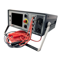
1. Connect the low-voltage RLC test leads to the motor leads.
2. Attach the RIC test template to the motor as described in the “Setting up Fixtures, Test
Accessories, and Lead Connections” chapter.
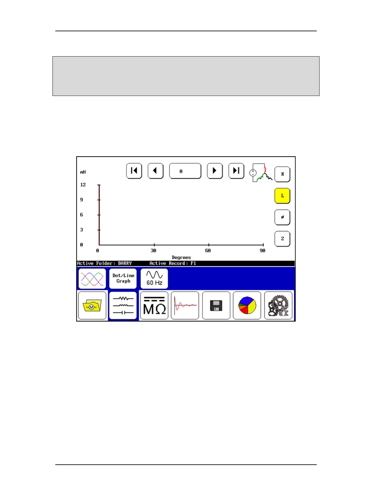
3. Check the Status Bar to ensure the Active Folder and Active Record fields display the
intended target destinations for your test data.
Figure 133. RIC test start screen.
4. Select the RLC mode icon in the Mode Menu then the RIC Mode icon in the Mode
Submenu. The starting screen should then look like the one shown above.
5. Starting at 0 degrees, push the Start (PTT) button to execute the first set of tests on
that position of the rotor. The Baker DX will automatically run three inductance tests—
one for each lead. The results of these tests are presented in the Display Area.
6. Move the rotor to the next shaft angle and press the PTT button again. As above, three
inductance tests will be performed and the results plotted on the screen.
7. Continue moving the shaft and running tests until the required number of angles have
been tested. (2-pole motors require 360° of shaft rotation to get a usable X-Y plot. 4-
pole motors require 180°, 6-pole motors require 120°, 8-pole motors require 90°, and so
on.)