Procedures for Testing with the DX Host
86 Baker DX 71-030 User Guide EN V10 www.megger.com
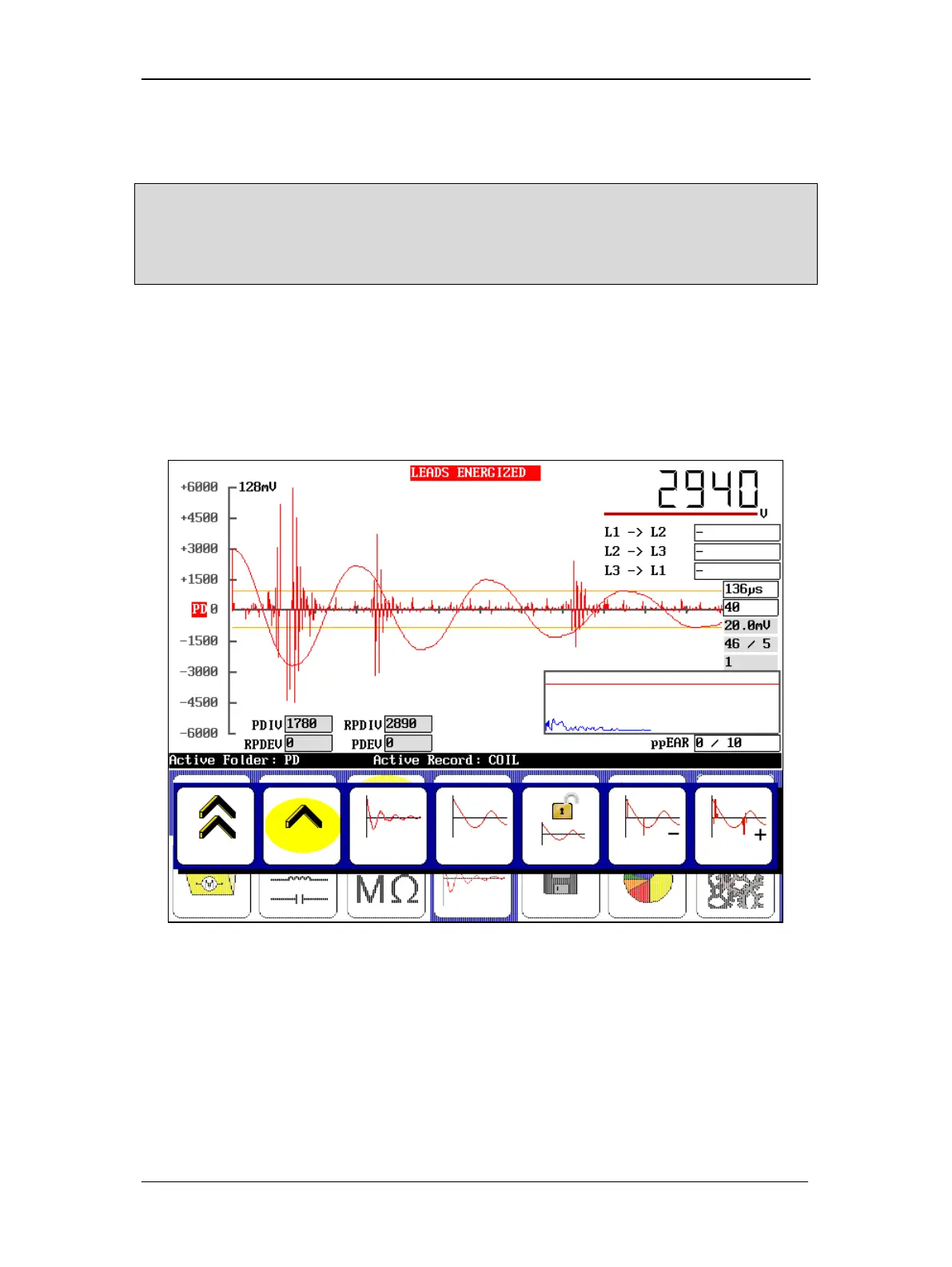
As the voltage increases, if there is partial discharge the PD waveform will display pulse activity
(indicating that partial discharge is occurring) when the expanded view is selected as shown in
the example below. The default view shows the PD waveform fully zoomed in.
NOTE: Refer to the “Options for Displaying PD Data During Testing” section below for more information on
display options for the PD and surge waveforms.
If these pulses are occurring and not meeting the threshold criteria, you might need to adjust the PD
threshold and PD # events values in the User Settings screen to appropriately indicate PD.
When PD activity exceeds the threshold value, a PD pulse occurs, the PDIV level is reached, and
the surge voltage value is recorded as PDIV.
A red PD indicator also begins to flash just left of the X-axis.
As you continue to increase the voltage, the activity will become more pronounced and more
frequent. At the point where more than 50 percent of the surge pulses have a PD pulse, the
software records the current surge voltage level as RPDIV.
Figure 94. Example of acquired inception voltages (PDIV and RPDIV).
7. To acquire the extinction voltages, hold down the PTT button and use the Voltage
Output Control knob to ramp down the voltage slowly and evenly.
8. Touch the Slow Ramp Rate icon to ramp down at a slower rate if desired.