Fd
THE
AUTOMATIC GEARBOX
OPERATIONS
KEY
TO ACTION
1.
Check manual linkage
adjustment.
12.
Examine
rear
clutch,
check valve, and seals. Check ■t
2.
Check ■uid level.
of tubes.
3.
Check adjustment
of down-shift and
throttle
valve
13.
Strip and clean valve bodies.
cable,
using
line
pressure gauge
and
tachometer,
14.
Strip and clean
governor
valve.
4.
Reduce
engine
idle Speed.
15.
Examine
parking pawl,
gear,
and internal linkage.
5.
Check adjustment
of front
band.
16.
Examine
one-way
clutch.
6.
Check front
servo
seals and
fit of tubes.
17. Strip
and
examine
pump
and
drive
tangs.
7.
Check front band
for
wear.
18.
Strip and
examine
gear
train.
8.
Check adjustment
of
rear
band.
19.
Adjust
starter
inhibitor switch inwards.
9.
Check
rear
servo
seal and
fit of
tubes.
20.
Adjust
starter
inhibitor
switch outwards.
10.
Check
rear
band
for
wear.
21. Replace
torque converter.
11.
Examine
front clutch and seals, also
forward
sun gear
22.
Examine
torque converter
drive plate for cracks
or
shaft sealing
rings.
Verify that
cup
plug
in
driven shaft
fracture.
is
not
leaking
or
dislodged.
23.
Check
engine
performance.
Section
F
d.7
Starter inhibitor and
reverse
light switch
PRESSURE
TEST—DOWN-SHIFT
VALVE CABLE
The
following
test
is
essential
to
determine
the
correct
adjustment
of the
down-shift and
throttle cable.
The
effects
of
cable
maladjustment
are
given
in Section
Fd.4, ‘FAULT
DIAGNOSIS’.
1.
With the carburetters
set at
normal idle,
check that
the crimped
stop
on
the
down-shift
valve
inner
cable
just
contacts
the abutment
on
the
outer
cable
2.
Remove
the line
pressure
take-off blanking
plug and
fit adaptor.
3.
Connect
tool
18G
677
Z
to
the
engine
and adaptor;
position
the
instrument
so
that
it
can
be
read
from
the
driving
seat.
4.
Apply the hand
brake and chock the
wheels.
5.
Select
‘N’ and
run
the
engine
until normal
operating
temperature
is
reached.
6.
With
the
engine
running
at
correct
idle speed check
that
a
line
pressure
of
55
to
65
lb./sq.
in. is
registered
on
the
instrument.
7.
Apply the foot
brake, select ‘D’,
increase
the
engine
speed
to
1,000
r.p.m.
when
a
pressure
reading of
90
to
100
1b./
sq.
in.
should be
registered.
8.
If the
pressure
reading
is
less than
the figure
given,
reset
the cable adjuster
so
that the
effective length of
the
outer
cable
is
increased.
If the
reading
is
higher,
readjust
to
decrease
the effective length
of
the
outer
cable.
Section
Fd.8
ADJUSTMENTS
Under
normal
operating
conditions
no
periodic adjustments
are
required.
SMGB.
Issue1.
15676
IMPORTANT—Apply the brakes
and
chock
the wheels
before checking
and
adjusting the switch. The
car may
move
off
if the
starter
is operated
with the selector
in
one
of
the drive
positions.
CHECKING
1.
Verify that the
switch
is
at
fault
by disconnecting
and
shorting the
leads
of
each
circuit
(‘1’
and ‘3’ terminals
are
for the
starter,
‘2’
and ‘4’
for
the
reverse
lights).
Check
that each
circuit
functions
regardless
of
the
selector
position.
ADJUSTING
2. Loosen the switch locknut,
using
tool 180
679.
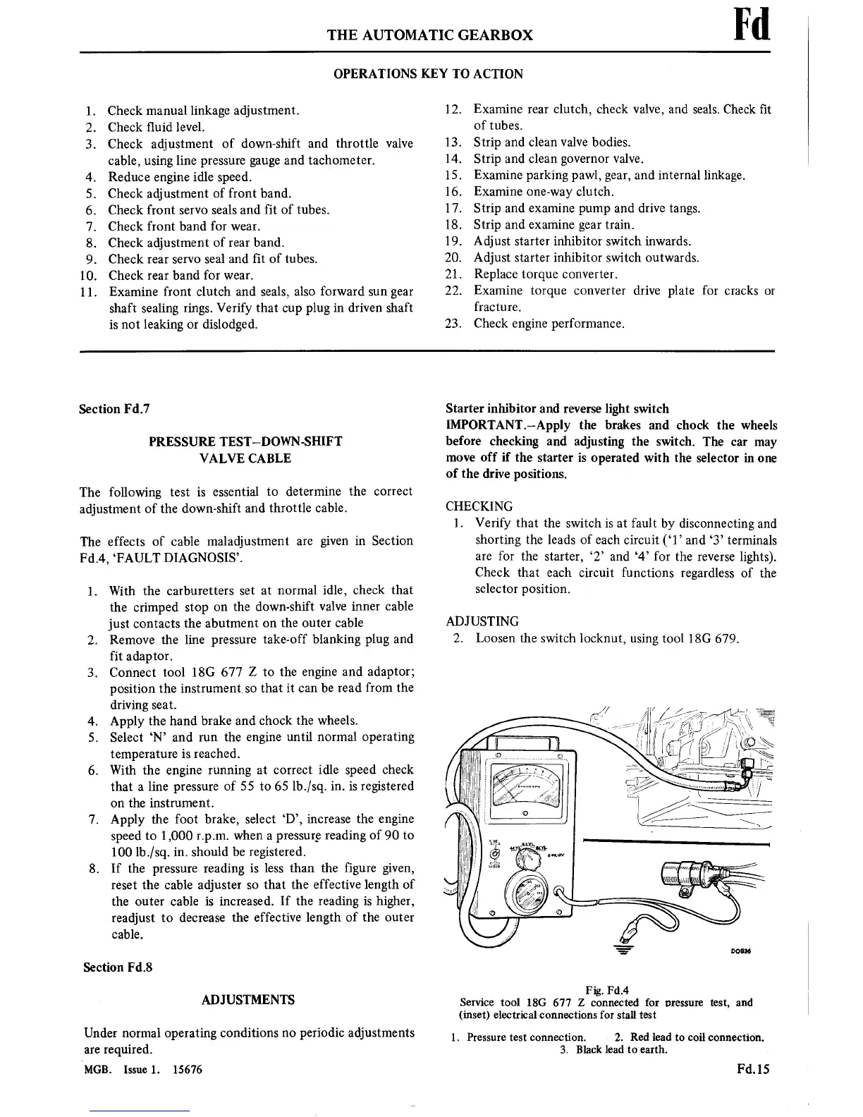
Fig. Fd.4
Service
tool 18G 677
Z
connected for
pressure
test,
and
(inset) electrical connections
for
stall
test
1.
Pressure
test
connection. 2.
Red lead
to
coil
connection.
3. Black lead
to
earth.
Fd.15