Note:
The CSP le is stored on the CD supplied with the device (Fieldbus directory of the
respective device). The current le is also available for download via the Internet:
http://www.minebea-intec.com
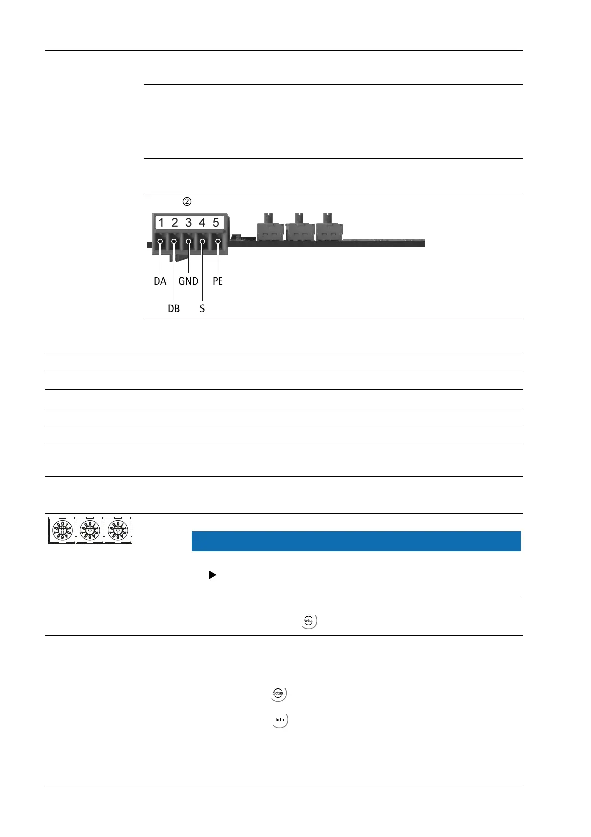
CC-Link terminal
Allocation of the 5-pole terminal block
Pin assignment Signal Description
1 -------------------- DA Communication RS-485 RxD/TxD (+)
2 -------------------- DB Communication RS-485 RxD/TxD (–)
3 ------------ GND Digital ground
4 -------------------- S Cable screen
5 -------------------- PE, according to AnyBus S-speci-
cation
Housing ground
4.6.8.1 Controls on eldbus card
NOTICE
The rotary switch settings will not be used.
Ensure that the three rotary switches (station no. and baud rate) are
set to position "9."
This setting is dened via - [Fieldbus parameter] [CC-Link].
4.6.8.2 Status indicator
Requirements:
- The items are dened via - [Display items]- [Fieldbus LEDs]; see Chapter 7.15.7.
- PR 1721/45 is selected via - [HW-Slots]- [Slot 2].
Transmitter in eld housing PR 5230 4 Device installation
Minebea Intec EN-94
 Loading...