Non-Fitted Calculations
Lynx II DSA User's Manual – 7096089 195
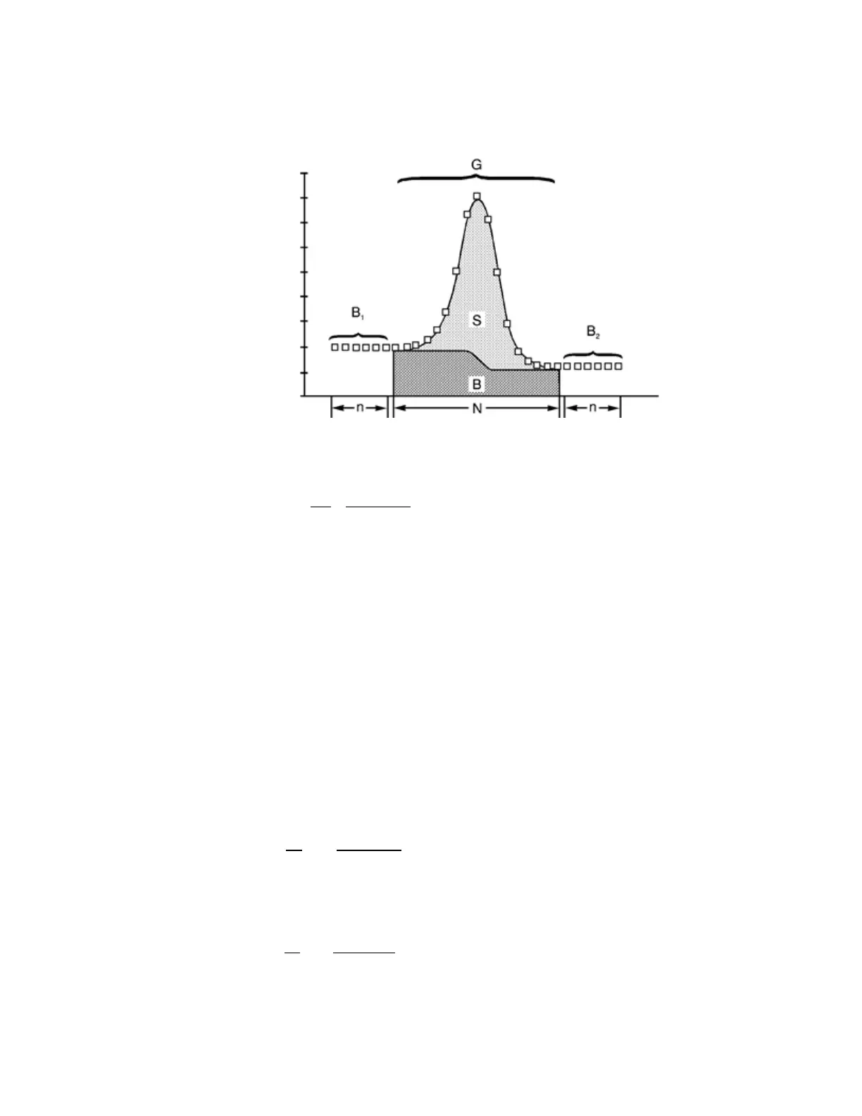
A step continuum, B, illustrated in Figure 35, is calculated from the sample spectrum
using the equation.
Figure 93 Parameters Used in a Step Continuum Calculation
(4)
( )
∑ ∑
= =
−
+=
N
1i
i
1j
j
121
y
nG
BB
n
B
B
where
y
i
is the counts per channel in channel i,
G is the total sum of counts (gross) in the peak ROI,
N is the number of channels in the peak ROI,
n is the number of continuum channels evaluated to the left side and the right side of the
ROI in determining B
1
and B
2
B
1
is the sum of counts in the continuum region to the left
of the peak, and
B
2
is the sum of counts in the continuum region to the right of the peak.
Equation (29) can also be written as
(5)
or (using a shorter notation for the partial sums P
i
)
(6)
( )
∑∑
==
−
+=
i
1j
j
N
1i
12
1
y
nG
BB
B
n
N
B
 Loading...