Chapter 4 System Setup
64 Lynx II DSA User's Manual - 7096089
• If your detector requires, and you've configured the Lynx II to supply negative high
voltage, connect the SHV cable between the preamp's HV INPUT connector and
the Lynx II's HV– connector.
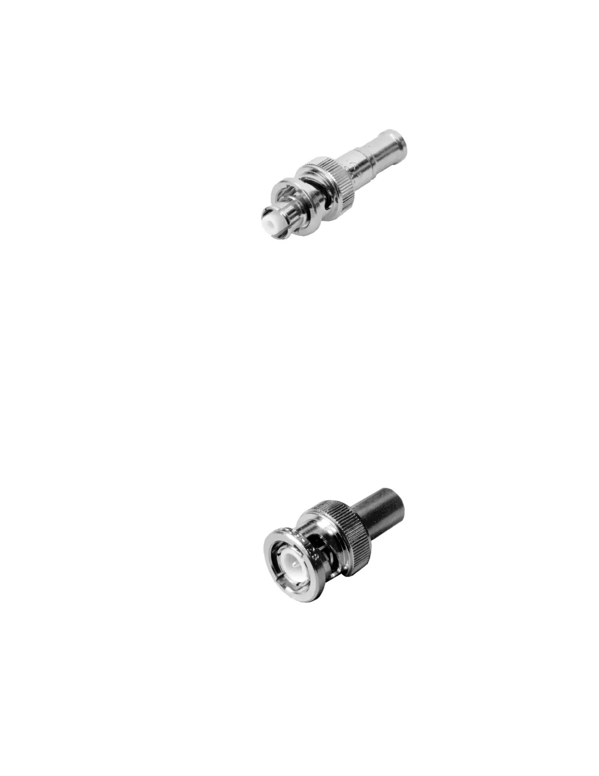
Figure 34: SHV Connector (cable end)
BNC Connections
Several BNC connections are often required. A typical BNC cable end is shown below.
1. Connect a BNC cable between the preamplifier's ENERGY connector and the
Lynx II's ENERGY connector.
2. Connect a BNC cable between the preamplifier's HV INH connector and the Lynx
II's HV INH connector.
3. For a system using CANBERRA's Model 2101 Transistor Reset Preamplifier,
connect a BNC cable between the 2101's INHIBIT connector and the Lynx II's
TRP INH connector.
Note: Take care to not connect the cable in Step 3 to the Model 2101's HV INHIBIT
connector; that connector has a different purpose.
Figure 35: BNC Connector (cable end)
 Loading...