17 - 5
17.4 Battery Voltage Low Detection and Battery Replacement
Example of alarm output to external device (lamp, buzzer, etc.)
The following describes an example of outputting the battery voltage low signal from
a FX series PLC to an external device with system information.
Condition: The Write Device is "D20" and all data is used (the button is
clicked on the setting screen of GT Designer2) for the system information
assignment.
D36 b12: Battery voltage low (System Signal 2-2)
Turned on upon a battery voltage drop.
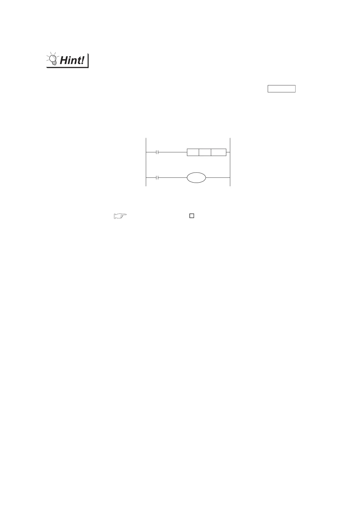
Used as shown below in the sequence program.
For details of system information, refer to the following.
GT Designer2 Version Screen Design Manual
Section 3.6 System Information Setting
Select All
M32
Output to external device of PLC
Activated the output upon battery
voltage low detection.
Battery voltage low
M8000
MOV D36 K4M20
RUN monitor
Y***
"*" indicates the output number at which the external device is connected.

 Loading...

