18 - 8
18.3 Troubleshooting in Bus Connection
18.3.2 Further locating error positions
17
MAINTENANCE AND
INSPECTION
18
ERROR MESSAGE
AND SYSTEM
ALARM
APPENDICES
18.3.2 Further locating error positions
If the function of the PLC cannot be recovered even when the module on which an error occurs is replaced
with a new one, the error may be caused by the effect from another module.
Disconnect the extension cables and bus connection cables in order from the modules starting from the
module located furthest from the operating position in the system, and check for the status of occurrence of
the error each time the cables are disconnected until the error does not occur.
The module or extension cables/bus-connection cables disconnected immediately before the error does not
occur are considered to cause the error.
Examples of the ways of further locating error positions are shown below. (When use the extension base unit
QnASCPU)
Repeat the examples 1 and 2 above to locate error positions.
Notes on narrowing the error part range
1. When disconnecting the extension base units in order, use only an END
instruction for the sequence program, and any error resulting from the sequence
program will not occur, and the status of occurrence of errors will be obtained
easily.
2. When the frequency of occurrence of an error is low, check the error by taking a
rather long time with the modules disconnected.
The checks stated above are effective to locate a noise invading route when the
mis-operation is caused by noise.
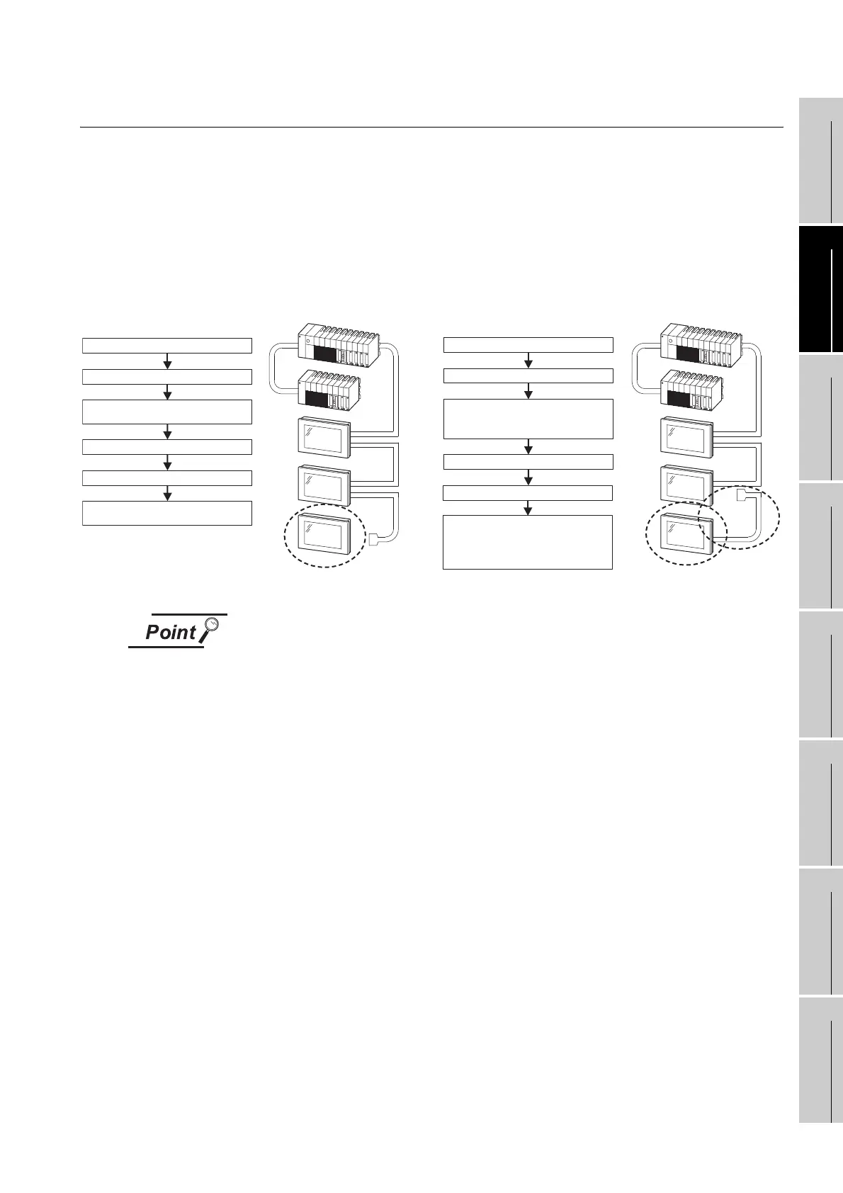
Example 1:
Turn off the power of the GOT.
Turn off the power of the PLC.
Disconnect the bus-connection cable
(IN side) from the final stage GOT.
Turn on the power of the PLC.
Turn on the power of the GOT.
If an error does not occur, the final
stage GOT may be faulty.
Disconnect the bus-connection cable
(OUT side) from the GOT located one
stage before the final stage.
Example 2:
Turn off the power of the GOT.
Turn off the power of the PLC.
Turn on the power of the PLC.
Turn on the power of the GOT.
If an error does not occur, the final
stage GOT and the bus-connection
cable before the final stage may be
faulty.

 Loading...

