4 - 2
4.2 Back Panel
1
OVERVIEW
2
SYSTEM
CONFIGURATION
3
SPECIFICATIONS
4
PART NAME
5
EMC DIRECTIVE
6
INSTALLATION
7
WIRING
8
OPTION
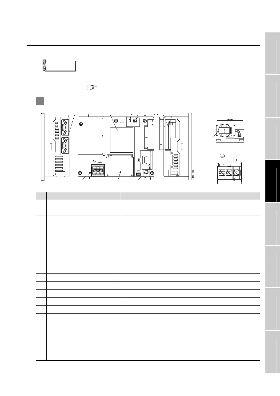
4.2 Back Panel
Remark
Connecting the back panel
For the connection to the controller (PLC, microcomputer board, bar code reader,
etc) or PC, refer to the following.
GOT 1000 Series Connection Manual
1 GT1155-QSBD, GT1150-QLBD
No. Name Specifications
1)
RS-232 interface
For communicating with controller (PLC, microcomputer board, bar code
reader, etc) or personal computer (OS installation, project data download,
transparent) (D-sub 9-pin male)
2)
RS-422 interface
For communicating with controller (PLC, microcomputer board, etc)
(D-sub 9-pin female)
3)
Hole for unit installation fitting
Hole for the inserting installation fittings (accessory) during the GOT
installation to the panel (4 holes at top and bottom)
4)
Rating plate (nameplate)
-
5)
CF card access LED Lit: CF card accessed Not lit: CF card not accessed
6)
CF card access switch
Switch for prohibiting access to CF card before removing the CF card from
the GOT
ON : CF card being accessed (CF card removal prohibited)
OFF : No access to CF card (CF card removal possible)
7)
CF card cover Open or close when inserting or removing the CF card.
8)
Option function board (option) Connect when using optional functions.
9)
Option function board cover Remove when using the option function board.
10)
Reset switch Hardware reset switch (Use an isolated rod to operate.)
11)
Battery cover Open or close when replacing the battery.
12)
Power terminal
Power terminal and FG terminal (for power supply (24VDC) to GOT and
grounding)
13)
Power terminal cover Open or close when connecting a power terminal. (Color: transparent)
14)
CF card interface Interface for installing the CF card to GOT
15)
CF card eject button Button for removing the CF card
16)
Battery
GT11-50BAT battery for storing clock data, alarm history and recipe data
(The project data is stored in the built-in flash memory.)
1)
2)
5)4)
10)11)12) 13)
Battery cover opened
CF card cover opened
16)
6)
7)
8) 9)
15)
14)
RS-232
CF CARD
I/F
ACCESS
BATTERY
24V DC
INPUT
RESET
+-
(FG)
CF
CARD
OFF ON
RS-422
Power supply terminal layout
(FG)
24V DC
INPUT
+-
3)3)
3)3)

 Loading...

