5 - 5
5.3 Wiring Precautions the Part which Matches the EMC Directives
5.3.1 About the cable used
1
OVERVIEW
2
SYSTEM
CONFIGURATION
3
SPECIFICATIONS
4
PART NAME
5
EMC DIRECTIVE
6
INSTALLATION
7
WIRING
8
OPTION
5.3 Wiring Precautions the Part which Matches the
EMC Directives
Connect and wire GOT equipment as instructed below.
If the GOT equipment is configured in a way that differs from the following instructions then the system will
not comply with EMC directives.
5.3.1 About the cable used
Any device which utilizes a data communication function is susceptible to the wider effects of local EMC
noise. Therefore, when installing any communication cables care should always be taken with the routing
and location of those cables. The GOT units identified on the previous page are compliant with the EMC
requirement when the following communication cables are used.
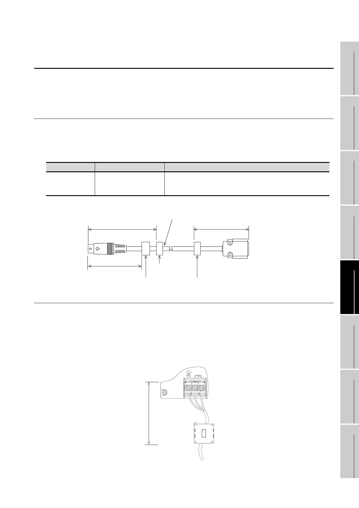
5.3.2 Method to connect the power wire and ground wire
The GT1155-QSBD and GT1150-QLBD unit requires an additional ferrite filter to be attached to the 24V DC
power supply cables. The filter should be attached in a similar manner as shown in the figure opposite, i.e.
the power cables are wrapped around the filter. However, as with all EMC situations the more correctly
applied precautions the better the systems Electro-magnetic Compatibility. The ferrite recommended is a
TDK ZCAT3035-1330 or similar. The ferrite should be placed as near to the 24V DC terminals of the
GT1155-QSBD and GT1150-QLBD as possible (which should be within 75mm of the GOT terminal).
GOT Unit Existing Cables User Made Cables
GT1155-QSBD
and
GT1150-QLBD
GT01-C30R4-8P modified as
shown in EX.1
Those cables need to be independently tested by the user to demonstrate EMC
compatibility when they are used with Mitsubishi GOT unit and FX2N Programmable
Controllers.
100mm(250mm)
140mm
GT01-C30R4-8P
Comes equipped
Added by user
GOT units
F = Ferrite core
Ex. Tokin - ESD-R-17S or simila
Programmable
controller
Added by user
F F F
24V DC
INPUT
+-
TDK
Up to
75mm

 Loading...

