7 - 3
7.1 Power Supply Wiring
7.1.2 The cause of malfunctions related wiring/Remedy
1
OVERVIEW
2
SYSTEM
CONFIGURATION
3
SPECIFICATIONS
4
PART NAME
5
EMC DIRECTIVE
6
INSTALLATION
7
WIRING
8
OPTION
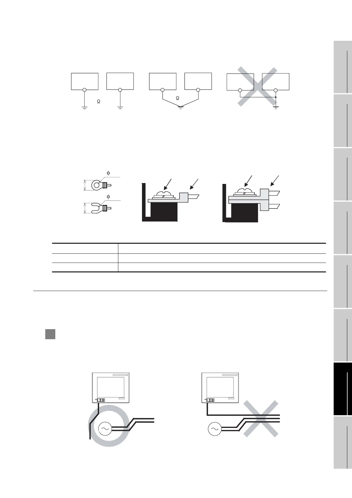
Make sure to carry out the followings for grounding.
• Carry out the independent grounding if possible.
• If the independent grounding is impossible, carry out the shared grounding as shown in fig.2) below.
• Use the cable of 2mm
2
or more for grounding.
Set the grounding point closer to the GOT to make the grounding cable short as possible.
Recommended terminal shape
7.1.2 The cause of malfunctions related wiring/Remedy
Grounding of the GOT may cause electric potential difference and noise interference, which may result in
GOT malfunctions.
These problems may be resolved by taking the following measures.
1 Wiring path of the GOT's ground cable and power line
Bundling the GOT's ground cable and power line together can cause interference noise, which may
result in malfunctions.
Keeping the GOT's ground cable and power line away from each other will help minimize noise
interference.
Cable size
For power supply: 0.75mm
2
min. For grounding: 2mm
2
min.
Solderless terminal M3 solderless terminal (applicable solderless terminal: RAV 1.25-3, V2-N3A and FV2-N3A)
Tightening torque 0.5 to 0.8N•m
GOT
Other
device
(1) Independent ground
...... Best condition
GOT
Other
device
(2) Shared grounding
...... Good condition
GOT
Other
device
(3) Common grounding
...... Not allowed
Grounding
(100 or less)
Grounding
(100 or less)
Terminal
screw
Solderless
terminal
Terminal
screw
6.2mm
or less
3.2
3.2
6.2mm
or less
When wiring one cable to
one terminal
When wiring two cables to
one terminal
Solderless
terminal
FG
Power supply for power equipment
Good : Wiring the ground cable away from the
power cable
FG
Power supply for power equipment
Bad : Bundling the ground cable and
the power cable
GRAPHIC OPERATION TERMINAL
GOT
1000
MITSUBISHI
GRAPHIC OPERATION TERMINAL
GOT
1000
MITSUBISHI

 Loading...

