6 - 2
6.1 Control Panel Inside Dimensions for Mounting GOT
1
OVERVIEW
2
SYSTEM
CONFIGURATION
3
SPECIFICATIONS
4
PART NAME
5
EMC DIRECTIVE
6
INSTALLATION
7
WIRING
8
OPTION
6.1 Control Panel Inside Dimensions for Mounting
GOT
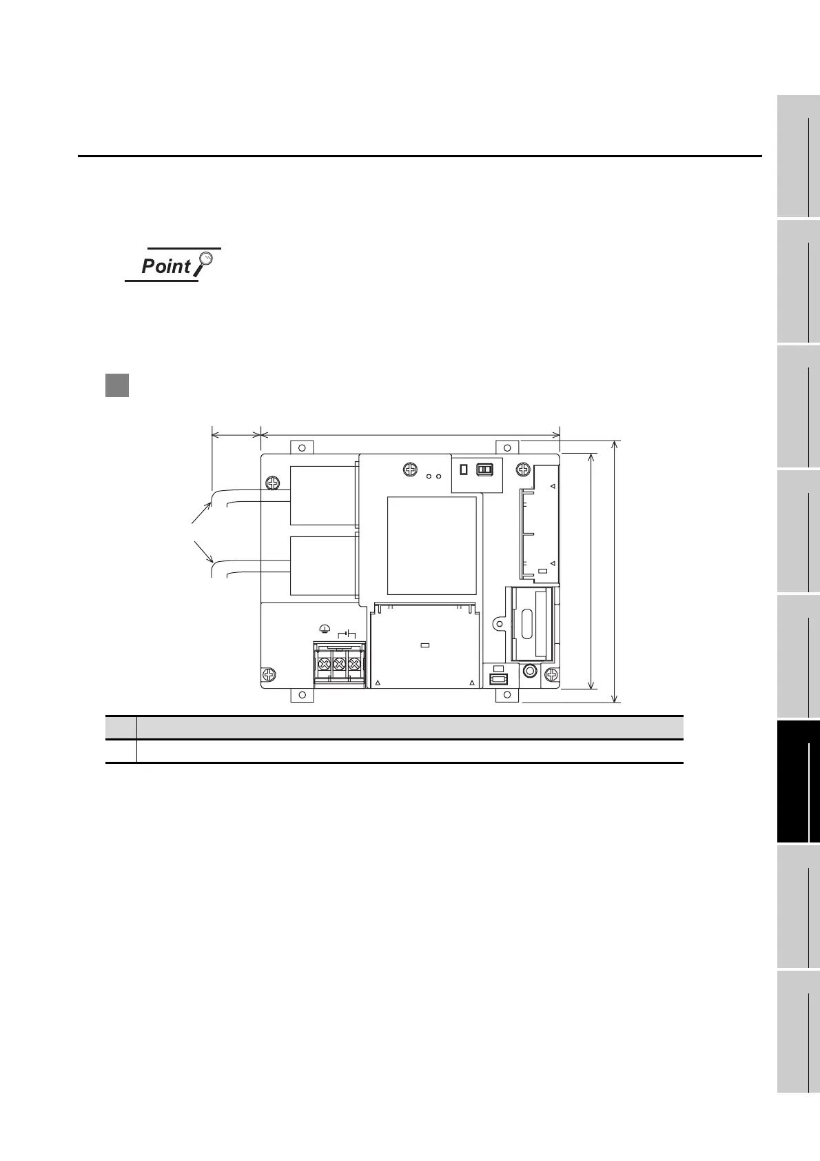
Mount the GOT onto the control panel while considering the following control panel inside dimensions.
Vertical installation of the GOT requires a space with the same dimensions as the horizontal installation
turned 90 degrees clockwise (seen from the display side).
Applicable cable
Some cables may need to be longer than the specified dimensions when connecting
to the GOT.
Therefore, consider the connector dimensions and bending radius of the cable as
well for installation.
1 GT1155-QSBD, GT1150-QLBD
No Name
1) PLC connection cable/PC connection cable
1)
152 (5.99")
120 (4.73")
30 (1.19")
140 (5.52")
RS-232
CF CARD
I/F
ACCESS
BATTERY
24V DC
INPUT
RESET
+-
(FG)
CF
CARD
OFF ON
RS-422
Unit: mm (inch)

 Loading...

