1 - 5
1
OVERVIEW
2
SYSTEM
CONFIGURATION
3
SPECIFICATIONS
4
PART NAME
5
EMC DIRECTIVE
6
INSTALLATION
7
WIRING
8
OPTION
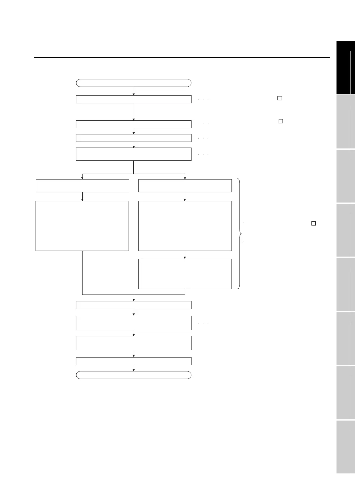
1.2 Rough Pre-operation Procedure
1.2 Rough Pre-operation Procedure
The outline procedure before operating GOT is shown.
When transferring data via a cable When transferring data via the CF card
Refer to 16. INSTALLATION OF
core OS, BOOTOS AND STANDARD
MONITOR OS in this manual for the
operations of GOT.
Refer to GT Designer2 Version
Screen Design Manual or Help functions of
GT Designer2.
Refer to Chapter 7 WIRING.
Refer to GT Designer2 Version
Basic Operation/Data Transfer Manual.
Install GT Designer2 in the PC.
Create project data.
Wire for the GOT power supply.
Install and download the OS program,
project data installed in the PC to the GOT.
1) Install the standard monitor OS,
communication driver, extended
functions OS, option OS to GOT.
2) Download the project data created
by the PC.
Write the OS, project data installed
in the PC in the CF card.
1) Write the standard monitor OS,
communication driver, extended function
OS, option OS in the CF card.
2) Write the project data created
by the PC in the CF card.
Install the CF card to GOT to install
and download the standard monitor OS,
communication driver, extended
function OS, option OS, project data
to the built-in flash memory.
Insert the CF card in the PC.
End
Start the monitor. (Display each screen.)
Connect the cable to GOT and the destination
connector.
Check the communication settings.
Turn on the GOT power and the system of the
connection destination.
Start
Connect GOT and PC with a USB cable
or RS-232 cable.
Refer to GT Designer2 Version
Basic Operation/Data Transfer Manual.
Refer to Chapter 8 OPTION.
Attach the option function board.
(Only when necessary)
Refer to GOT1000 Series Connection Manual.

 Loading...

