7 - 5
7.1 Power Supply Wiring
7.1.2 The cause of malfunctions related wiring/Remedy
1
OVERVIEW
2
SYSTEM
CONFIGURATION
3
SPECIFICATIONS
4
PART NAME
5
EMC DIRECTIVE
6
INSTALLATION
7
WIRING
8
OPTION
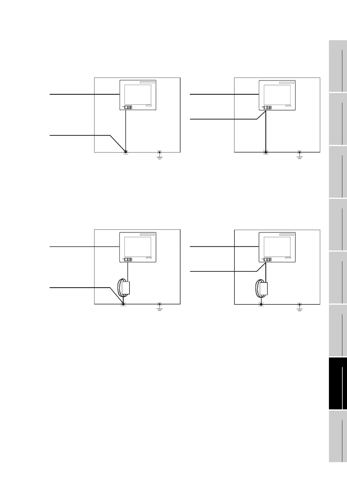
• Remedy 1 (Refer to the figures Remedy 1-1 and 1-2 below.)
If the electric potential difference between the ground cable and the panel that houses the GOT is creating
problems, connect the ground cable to the panel also.
If the wiring method as shown in Remedy 1-1 is not feasible, follow Remedy 1-2.
If taking Remedy 1 worsens noise interference, taking Remedy 2 may alleviate it.
• Remedy 2 (Refer to the figures Remedy 2-1 and 2-2 below.)
Attach a ferrite core to the cable if noise from the GOT panel has adverse effects on the GOT when Remedy
1 is taken.
Wind the wire around the ferrite core several times (approx. 3 times), if a ferrite core is used.
If the wiring method as shown in Remedy 2-1 is not feasible, follow Remedy 2-2.
Panel grounding
Remedy 1-1
Use the thickest
cable possible.
Remedy 1-2
GRAPHIC OPERATION TERMINAL
GOT
1000
MITSUBISHI
GRAPHIC OPERATION TERMINAL
GOT
1000
MITSUBISHI
FG
Ground cable from
the panel that
houses control
equipment
Connection cable
Panel grounding
FG
Connection cable
Use the thickest
cable possible.
Ground cable from
the panel that
houses control
equipment
Ferrite core Ferrite core
GRAPHIC OPERATION TERMINAL
GOT
1000
MITSUBISHI
GRAPHIC OPERATION TERMINAL
GOT
1000
MITSUBISHI
Panel grounding
Remedy 2-1
Remedy 2-2
FG
Connection cable
Panel grounding
FG
Connection cable
Use the thickest
cable possible.
Ground cable from
the panel that
houses control
equipment
Use the thickest
cable possible.
Ground cable from
the panel that
houses control
equipment

 Loading...

