Issue 2.0
SV9100 Networking Manual 2-5
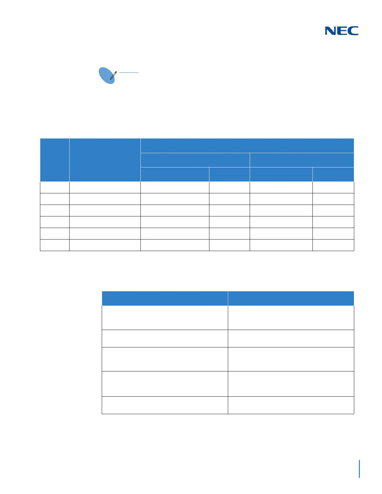
4.2.1 Card Interface Slot Assignment (PRG 10-03 ETU Setup)
The following table provides information for assigning the blade interface
slots.
4.2.2 Digital Trunk Assignments
Use the table below to make the appropriate assignments for digital trunks.
It is assumed that the systems were defaulted (first power on) with the
following blades installed as described below.:
Slot
Card Type During 1st
Power On
Card Type and Ports
System A System B
Card Type Ports Card Type Ports
1
GCD-CP10/GPZ-IPLE GCD-CP10/GPZ-IPLE Trunks 5 ~28 GCD-CP10/GPZ-IPLE Trunks 5~28
2
GCD-8DLCA GCD-8DLCA Station 1~8 GCD-8DLCA Station 1~8
3
GCD-8DLCA GCD-8DLCA Station 9~16 GCD-8DLCA Station 9~16
4
None None N/A None N/A
5
GCD-4COTC GCD-4COTC Trunks 1~4 GCD-4COTC Trunks 1~4
6
None None N/A None N/A
System A System B
Program 10-03-01
Insert GPZ-IPLE on GCD-CP10 in Chassis 1, Slot 1.
Verify PRG 10-03-01 (ETU Setup).
Program 10-03-01
Insert GPZ-IPLE on GCD-CP10 in Chassis 1, Slot 1.
Verify PRG 10-03-01 (ETU Setup).
Program 10-19-01
Assign DSP Resources 001~024 as CCIS (LK4).
Program 10-19-01
Assign DSP Resources 001~024 as CCIS (LK4).
Program 10-68
Assign the Trunk Type as CCIS with the Start Port
as 5 and Number of Port 24.
Program 10-68
Assign the Trunk Type as CCIS with the Start Port
as 5 and Number of Port 24.
Program 14-05-01
Assign Trunks 5~28 in Trunk Group 10.
Program 14-05-01
Assign Trunks 5~28 in Trunk Group 10.
Program 22-02-01
Set Trunks 5~28 as Tie Line (LK6).
Program 22-02-01
Set Trunks 5~28 as Tie Line (LK6).

 Loading...


