Issue 2.0
5-18 Network Design Considerations
Protocol Structure - IEEE 802.1p: LAN Layer 2 QoS
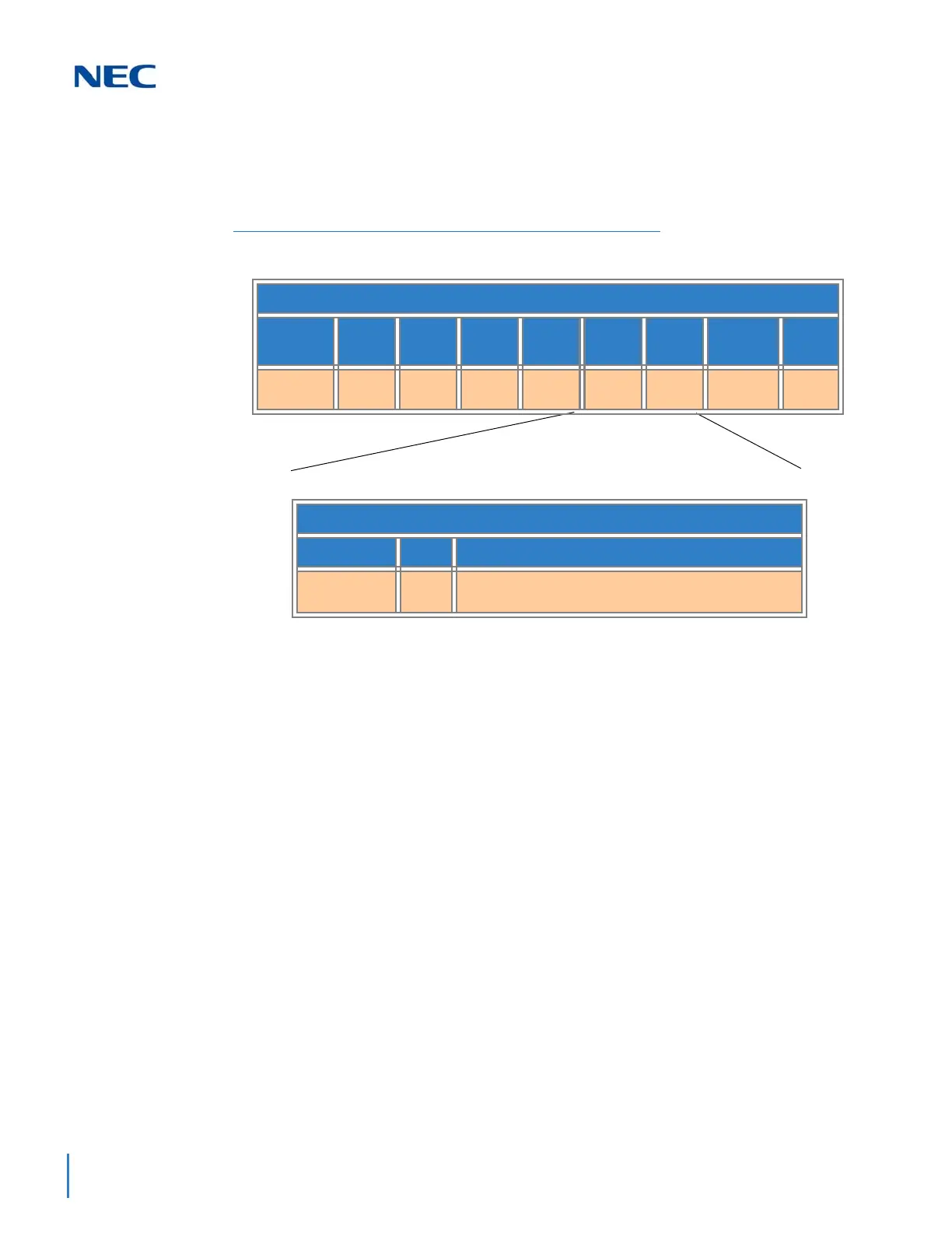
Figure 5-6 Protocol Structure for Layer 2 QoS illustrates the format of an Ethernet
frame and the User Priority field that is used for Layer 2 QoS.
The following define the fields used for the protocol structure:
Preamble (PRE) - The PRE is an alternating pattern of ones and zeros that tells
receiving stations a frame is coming, and synchronizes frame-reception portions
of receiving physical layers with the incoming bit stream.
Start-of-frame delimiter (SFD) - The SOF is an alternating pattern of ones and
zeros, ending with two consecutive 1-bits indicating that the next bit is the left-
most bit in the left-most byte of the destination address.
Destination Address (DA) - The DA field identifies which station(s) should
receive the frame.
Source Addresses (SA) - The SA field identifies the sending station.
Tag Protocol Identifier (TPID) - The defined value of SV9100 in hex. When a
frame has the EtherType equal to SV9100, this frame carries the tag IEEE 802.1Q
/ 802.1P.
Tag Control Information (TCI) - The field including user priority, Canonical
format indicator and VLAN ID.
Figure 5-6 Protocol Structure for Layer 2 QoS
Expanded View of TCI Field
3 Bits 1 Bit 12 Bits
User Priority CFI Bits of VLAN ID (VID) to identify possible VLA
Ns
IEEE 802.1Q Tagged Frame for Ethernet
7
Bytes
1
Byte
6
Bytes
6
Bytes
2
Bytes
2
Bytes
2
Bytes
42~1496
Bytes
4
Bytes
Preamble SFD DA SA TPID TCI Type
Length
Data CRC

 Loading...


