Issue 2.0
SV9100 Networking Manual 13-7
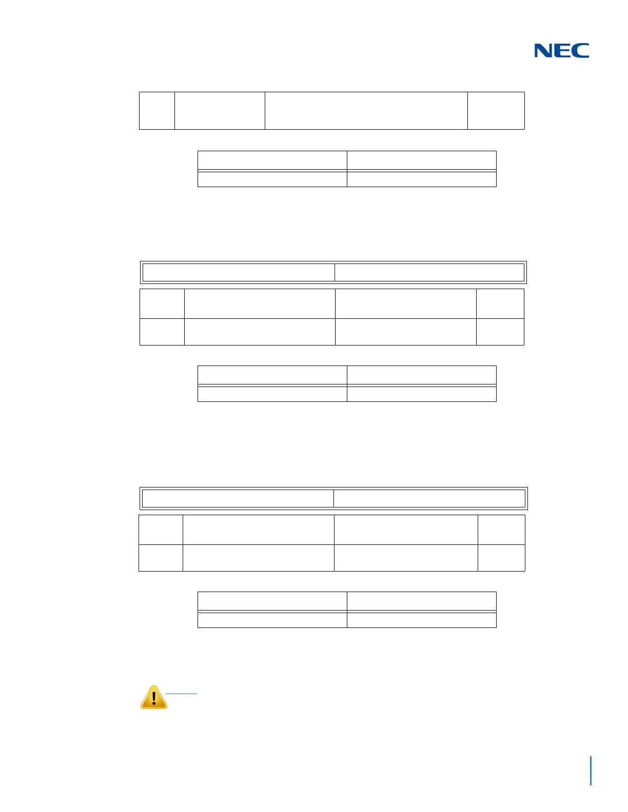
Example:
° 10-03-10 : PCB Setup - Master/Slave System
Determine which system will be the master system and which one(s) will be the slave system(s). If one end of
the line is set as the Master, the other end of the line must be set as the Slave. The choice of Master/Slave is
determined by the ISDN clock available at the SV9100 System, see the Section 5 for further detail.
Example:
° 10-03-11 : PCB Setup - Networking System Number
The Networking ID is used to select the access route for dialed digits. You can choose any number 0 to 50 (0
equals no operation). This ID is used when setting the numbering plan for the networked systems. The same ID
number must be set in both 10-03-11 and 11-01. Refer to
2.5 Numbering Plan in on page -12 for more on
the numbering plan settings.
Example:
2.3 AspireNet IP
03 Connection Type 0 = Point-to-Multipoint (not available for
Networking)
1 = Point-to-Point
0
System – A System – B
1: Point-to-Point 1: Point-to-Point
ISDN Line Number 1-4
Item
No.
Item Input Data Default
10 Master/Slave System
(Network Mode Only)
0- Slave System
1- Master System
0
System – A System – B
1: Master 2: Slave
ISDN Line Number 1-4
Item
No.
Item Input Data Default
10 Networking System Number (Net-
work Mode Only)
0-50 0
System – A System – B
Networking ID: 1 Networking ID: 1
As with any Voice Over IP (VoIP) implementation, there are several
issues that should be considered when setting up AspireNet IP

 Loading...


