6-50
D PID Control Settings
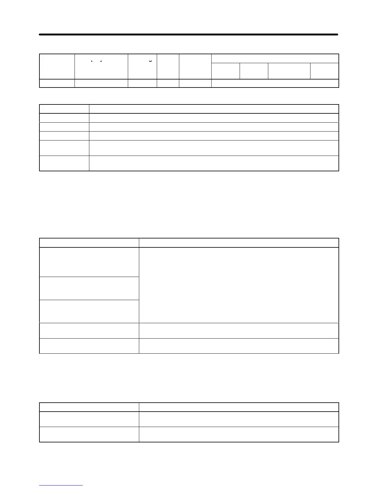
Parameter Display name Setting Units Default
Valid access levels
number
range setting
V/f
Control
V/f with
PG
Open Loop
Vector
Flux
Vector
b5-01 PID Mode 0 to 4 --- 0 Advanced
This parameter cannot be changed during operation.
Set value Contents
0 PID disabled
1 PID enabled (Deviation signal is put through derivative control.)
2 PID enabled (Feedback signal is put through derivative control.)
3 PID enabled. (Frequency reference and PID control/deviation signal are put through
derivative control.)
4 PID enabled. (Frequency reference and PID control/feedback signal are put through
derivative control.)
Note 1. To
enable PID control, set 1 through 4. (Normally 2 or 4 is used for measured-value derivative
PID control.)
Note 2. If
the target speed of the application (e.g., tension control) is rather
clear and PID control is
required for fine tuning, set 3 or 4 for frequency reference and PID control.
Setting Target Values for PID Control
The following guidelines can be used to select target values for PID Control.
c Contents
Frequency reference input,
voltage: Terminal 13
The frequency source selected for parameter b1-01 is used as the
target value.
Note 1. If
the PID control target value is not set for a multi-function ana
-
lo
Setting via Digital Operator
,
H3-09), then the setting of b1-01 is used automatically.
Note 2. Frequency references 2 to 8 and the inching reference are
enabled regardless of the setting of b1 01
Option frequency reference
ena
.
Note 3. Operation
will be clearer if o1-03 is set to 1 (% unit) when set
-
ting from a Digital Operator.
Multi-function analog input:
Terminal 16
Set C for the function selection of multi-function analog input terminal
16 (H3-05) to select the PID target value.
Frequency reference, current:
Terminal 14
Set C for the function selection of frequency reference (current)
terminal 14 (H3-09) to select the PID target value.
Note When using different input signals for frequency reference and PID control, set the PID target
value to either a multi-function analog input or the frequency reference (current).
Setting Feedback Values for PID Control
The following guidelines can be used to select feedback values for PID Control.
c Contents
Multi-function analog input:
Terminal 16
Set B for the function selection of multi-function analog input terminal
16 (H3-05) to select the PID feedback value.
Frequency reference, current:
Terminal 14
Set B for the function selection of frequency reference (current)
terminal 14 (H3-09) to select the PID feedback value.
Note 1. Use the gain and bias settings for the analog inputs to adjust the feedback value.
Advanced Operation Chapter
6