Chapter 3: Robot Installation
l
Drill a dowel pin hole Ø6 mm, H7 for the internally threaded positioning pin,
10to 15 mm deep.
2.
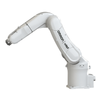
Locate two alignment pins, one round and one diamond-shaped, supplied as part of the
robot bundle.
3.
Drive the diamond-shaped pin into one Ø6, H7 hole in the robot base so that it is ori-
ented as shown in the preceding figure.
4.
Drive the internally threaded alignment pin into the other Ø6, H7 hole in the robot base.
NOTE: Be sure to use the alignment pins. It can minimize positional devi-
ations that may be caused by the removal/installation of the robot for
maintenance and reduce vibration during operation.
5.
Set the robot into place on the robot mount. When transporting the robot, follow the
instructions given in Transporting the Robot on page 23.
6.
Secure the robot to the mount with four bolts:
l
Bolt: M10, strength class: 12.9
l
Tightening torque: 70 ± 14 N·m (52 ± 10 ft-lbf)
For threaded M10 holes, use plain washers and 30 mm M10 bolts.
For 12 mm thru holes, use plain and lock washers on both sides.
3.6 Grounding the Robot
Ground the grounding terminal of the robot with a wire of 12 AWG or larger. Ground res-
istance must be less than 10 Ohms. See Grounding the Robot System on page 77.
3.7 Mounting the Front Panel
The Front Panel must be installed outside of the workspace.
NOTE: European standards require that the remote High Power push-button be
located outside of the workspace of the robot.
05173-060 M Viper 650/850 Robot with eMB-40/60R User's Guide 27

 Loading...


