Chapter 5: System Installation
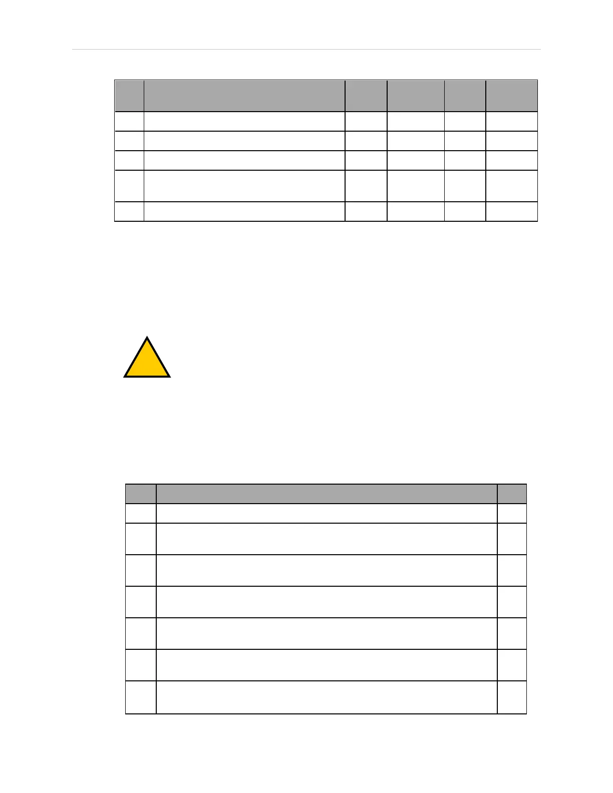
Part Cable and Parts List Part # Standard Option User-
Supplied
S Ethernet switch, if used n/a X X
T Camera and cable n/a X X
U Grounding Terminal, M5 n/a X
V Arm Power/Signal Cable 05438-
000
X
W eMB-40/60R Interface Panel n/a X
The XUSR, XMCP, and XFP jumpers intentionally bypass safety connections so you can test
the system functionality during setup.
The XUSR is for a User E-Stop/Safety Gate or a Muted Safety Gate. The jumper plug is required
if neither of these is used.
Either the Front Panel or the Front Panel plug must be used.
Either the T20 Pendant , T20 Bypass Plug, or XMCP Jumper Plug must be used.
WARNING: Under no circumstances should you run a Viper system, in pro-
duction mode, with all three jumpers installed. This would leave the system
with no E-Stops.
Cable Installation Overview
Power requirements for the SmartVision MX industrial PCare covered in that user guide. For
24 VDC, both the Viper robot and a SmartVision MX can usually be powered by the same
power supply.
Step Connection Part
1 Connect eAIB XSYSTEM cable to XSYSTEM on eMB-40/60R. A
2 Connect a user E-Stop or Muted Safety Gate to the eAIB XSYSTEM cable
XUSR connector or
B
2a verify XUSR jumper plug is installed in eAIB XSYSTEM cable XUSR con-
nector.
C
3 Connect Front Panel cable to Front Panel and eAIB XSYSTEM cable XFP con-
nector or
D, E
3a if no Front Panel, install FP jumper on eAIB XSYSTEM cable XFP connector.
See NOTE after table.
F
4 Connect T20 Pendant adapter cable to eAIB XSYSTEM cable XMCP con-
nector or
J, K
4a if no T20 Pendant, install XMCP jumper
or
G
or
05173-060 M Viper 650/850 Robot with eMB-40/60R User's Guide 59