Home
Oracle
Server
X6-2
Page 183
Oracle X6-2 - Page 183
284 pages
Manual
Save Page as PDF
To Next Page
To Next Page
To Previous Page
To Previous Page
Loading...
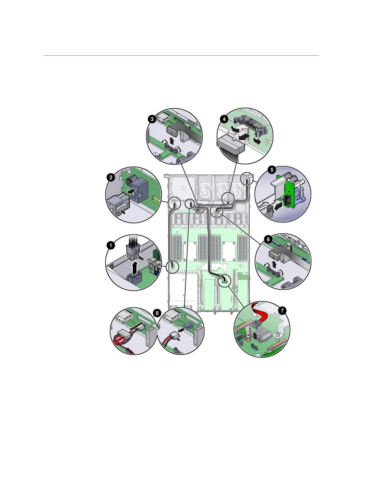
Removing the Power
, FIM, Disk Backplane Data, and DVD Cables
Servicing FRUs
183
FIGURE 33
Removing the Power
, FIM, Auxiliary Power/Signal, and DVD Cables
4.
T
o remove the Auxiliary power and signal cable, perform these steps:
182
184
Table of Contents
Main Page
Table of Contents
5
Using this Documentation
11
Product Documentation Library
11
Feedback
11
About the Oracle Server X6-2
13
Product Description
13
About Controls and Connectors
14
Front Panel Controls and Indicators
14
USB 2.0 Connectors
15
Server Back Panel View
16
Related Information
16
About System Components
17
Illustrated Parts Breakdown
17
About System Components
18
Customer-Replaceable Units
19
Field-Replaceable Units
20
Related Information
20
Server Internal Cables
20
Servicing Crus that Do Not Require Server Power-Off
20
Servicing Crus that Require Server Power-Off
20
Server Internal Cables
21
Troubleshooting and Diagnostics
23
Troubleshooting Server Component Hardware Faults
23
Troubleshooting Server Hardware Faults
24
Troubleshooting and Diagnostic Information
27
Troubleshooting Using the Server Front and Rear Panel Status Indicators
28
Default Chapter
29
Server System-Level Status Indicators
29
Server Fan Status Indicators
30
Storage Drive Status Indicators
30
Network Management Port Status Indicators
31
Power Supply Status Indicators
31
Ethernet Ports Status Indicators
32
Motherboard Status Indicators
32
Troubleshooting System Cooling Issues
33
Troubleshooting Power Issues
35
Managing Server Hardware Faults through the Oracle ILOM Fault Management Shell
37
Troubleshooting with Diagnostic Tools
38
Diagnostic Tools
38
Diagnostic Tool Documentation
39
Attaching Devices to the Server
40
Attach Devices to the Rear of the Server
40
Rear Panel Connector Locations
40
Configuring Serial Port Sharing
42
Ethernet Port Boot Order and Device Naming
43
Server Operating System Names for the Nvme Storage Drives
43
Rear Panel Pinhole Switches
44
Getting Help
45
Contacting Support
45
Locating the Chassis Serial Number
46
Preparing for Service
47
Safety Precautions
47
Safety Symbols
48
Electrostatic Discharge Safety
48
FRU Key Identity Properties (KIP) Automated Update
49
Related Information
50
Required Tools
50
Preparing the Server for Component Replacement
50
Powering down the Server
51
Power down Server Gracefully Using the Power Button
53
Use the Oracle Ilom Cli for Immediate Shutdown
54
Use the Oracle Ilom Web Interface for Immediate Shutdown
55
Disconnect Cables from the Server
56
Extend the Server to the Maintenance Position
56
Remove the Server from the Rack
58
Open the Server Fan Door
59
Take Antistatic Measures
59
Remove the Server Top Cover
60
Servicing Crus that Do Not Require Server Power-Off
63
Servicing Storage Drives (CRU)
63
Storage Drive Failure and RAID
64
Storage Drive Locations and Numbering
64
Storage Drives Hot-Plug Conditions
64
Storage Drive Status Indicators
65
Removing and Replacing a HDD or SSD Storage Drive
66
Grasp the Latch and Pull the Drive out of the Drive Slot/Consider Your Next Steps
67
Figure 10
68
Removing and Replacing an Nvme Storage Drive Using Oracle Solaris
69
Grasp the Latch and Pull the Drive out of the Drive Slot
70
Servicing Fan Modules (CRU)
75
Consider Your Next Steps
70
If You Are Replacing the Drive, Continue to
70
Removing and Replacing an Nvme Storage Drive Using Oracle Linux
72
Drive" on Page
74
Server Filler Panels " on Page
74
The Drive
74
Related Information
75
Storage Drive Failure and RAID
75
Storage Drive Status Indicators
75
Storage Drives Hot-Plug Conditions
75
Remove a Fan Module
76
Install a Fan Module
79
Servicing Power Supplies (CRU)
80
Power Supply Status Indicators
81
Remove a Power Supply
81
Oracle Server X6-2 Service Manual • June
82
Install a Power Supply
83
Servicing Crus that Require Server Power-Off
85
Servicing the Dimms (CRU)
85
Related Information
86
Default Chapter
86
DIMM and Processor Physical Layout
86
DIMM Population Scenarios
87
DIMM Population Rules
88
Populating Dimms for Optimal System Performance
88
DIMM Operating Speeds
92
DIMM Rank Classification Labels
92
Inconsistencies between DIMM Fault Indicators and the BIOS Isolation of Failed Dimms
92
Using the Server Fault Remind Button
92
Identify and Remove the Failed DIMM
93
Install a DIMM
95
Related Information
95
Servicing Pcie Risers (CRU)
97
Pcie Riser Location and Differences
98
Remove a Pcie Riser from Pcie Slot 1 or 2
99
Install a Pcie Riser into Pcie Slot 1 or 2
101
Remove the Pcie Riser from Pcie Slots 3 and 4
103
Install the Pcie Riser into Pcie Slots 3 and 4
105
Servicing Pcie Cards (CRU)
108
Pcie Slot Characteristics
108
Remove a Pcie Card from Pcie Slot 1 or 2
109
Install a Pcie Card in Pcie Slot 1 or 2
110
Remove a Pcie Card from Pcie Slot 3
111
Install a Pcie Card in Pcie Slot 3
112
Servicing the Internal USB Flash Drives (CRU)
113
Remove an Internal USB Flash Drive
114
Install an Internal USB Flash Drive
115
Servicing the Battery (CRU)
116
Remove the Battery
116
Install the Battery
117
Servicing Frus
119
Servicing Processors (FRU)
120
Selecting the Correct Processor Removal and Replacement Tool
120
Remove a Processor
125
Install a Processor
131
Power Supplies
136
Servicing the Oracle Pcie Nvme Switch Card (FRU)
137
Remove the Oracle Pcie Nvme Switch Card from Pcie Slot 1
138
Install the Oracle Pcie Nvme Switch Card in Pcie Slot 1
139
Servicing the Internal HBA Card (FRU)
140
Remove the Internal HBA Card from Pcie Slot 4
141
Install the Internal HBA Card in Pcie Slot 4
145
Servicing the Disk Backplane (FRU)
150
Remove the Disk Backplane
150
Install the Disk Backplane
153
Servicing the DVD Drive (FRU)
156
Remove the DVD Drive
156
Install the DVD Drive
158
Servicing the Front Indicator Module (FRU)
158
Remove the Front Indicator Module
159
Install the Front Indicator Module
161
Servicing the Motherboard (FRU)
162
Remove the Motherboard
162
Install the Motherboard
169
Servicing the Internal HBA SAS Cable Assembly
173
Remove the Internal HBA SAS Cable Assembly
173
Install the Internal HBA SAS Cable Assembly
176
Servicing the Nvme Cables
177
Removing the Nvme Cables
178
Install the Nvme Cables
180
Servicing the Power, FIM, Disk Backplane Data, and DVD Cables
181
Removing the Power, FIM, Disk Backplane Data, and DVD Cables
182
Install the Power, FIM, Disk Backplane Data, and DVD Cables
184
Returning the Server to Operation
187
Removing and Installing Server Filler Panels
187
Remove and Install Filler Panels
188
Install the Server Top Cover
188
Remove Antistatic Measures
190
Reinstall the Server into the Rack
190
Return the Server to the Normal Rack Position
191
Reconnect Data Cables and Power Cords
193
Power on the Server
194
Identifying the Server Ports
195
Gigabit Ethernet Ports
195
Network Management Port
196
Oracle Server X6-2 Service Manual • June
196
Serial Management Port
197
Video Connector
198
USB Ports
199
Setting up BIOS Configuration Parameters
201
Managing the BIOS Configuration
201
Accessing the BIOS Setup Utility
202
BIOS Setup Utility Menus
202
Access BIOS Setup Utility Menus
203
BIOS Key Mappings
203
Navigate BIOS Setup Utility Menus
205
Using UEFI
206
Selecting Legacy BIOS or UEFI Boot Mode
206
Switching between Legacy BIOS and UEFI Boot Modes
207
Configuration Utilities for Add-In Cards
208
UEFI Boot Mode Advantages
208
Using BIOS for Legacy Option ROM Resource Allocation
209
Common BIOS Setup Utility Tasks
210
Default Chapter
210
Verify BIOS Factory Default Settings
210
Select Legacy BIOS or UEFI Boot Mode
211
Select the Boot Device
213
Configure TPM Support
215
Configure SP Network Settings
217
Configure Option ROM Settings
220
Configure I/O Resource Allocation
223
Exit BIOS Setup Utility
224
BIOS Setup Utility Menu Options
227
BIOS Main Menu Selections
227
BIOS Advanced Menu Selections
231
BIOS Advanced Menu Processor Configuration Options
232
BIOS Advanced Menu CPU Power Management Configuration Options
233
BIOS Advanced Menu Memory Configuration Option
234
BIOS Advanced Menu USB Ports Options
234
BIOS Advanced Menu Serial Port Console Redirection Options
235
BIOS Advanced Menu Trusted Computing Options
236
BIOS Advanced Menu Network Stack Options
237
BIOS Advanced Menu BMC Network Configuration Options
238
BIOS Advanced Menu Iscsi Configuration Options
241
BIOS Advanced Menu Ethernet Controller Options
243
BIOS IO Menu Selections
244
BIOS IO Menu PCI Subsystem Settings Options
245
BIOS IO Menu I/OAT Configuration Options
246
BIOS IO Menu IO Virtualization Options
246
BIOS IO Menu Add in Cards Options
247
BIOS IO Menu Internal Devices Options
247
BIOS Boot Menu Selections
248
BIOS Exit Menu Selections
249
Monitoring Components and Identifying SNMP Messages
251
Monitoring Component Health and Faults Using Oracle ILOM
251
Monitoring System Components
252
System Chassis Components
253
Cooling Unit Components
255
Disk Backplane Components
255
Memory Device Components
256
Power Unit Components
257
Processor Components
258
System Board Components
259
System Firmware Components
261
Hard Disk Drive Components
262
Identifying SNMP Trap Messages
263
Environmental Events
263
Hard Disk Drive Events
265
Power Events
266
Fan Events
270
Memory Events
271
Entity Presence Events
276
Physical Presence Events
277
Index
279
Oracle Server X6-2 Service Manual • June
280
Related product manuals
Oracle X6-2-HA
473 pages
Oracle X6 series
126 pages
Oracle Server X6-2
144 pages
Oracle EXADATA X6-2
337 pages
Oracle X7-2
312 pages
Oracle X5-2
180 pages
Oracle X8-2L
318 pages
Oracle X4 series
240 pages
Oracle X7 series
118 pages
Oracle EXADATA X5-2
262 pages
Oracle SUN Fire X4640
44 pages
Oracle Sun Fire X4800
92 pages