Servicing the DIMMs (CRU)
Servicing CRUs That Require Server Power-Off 91
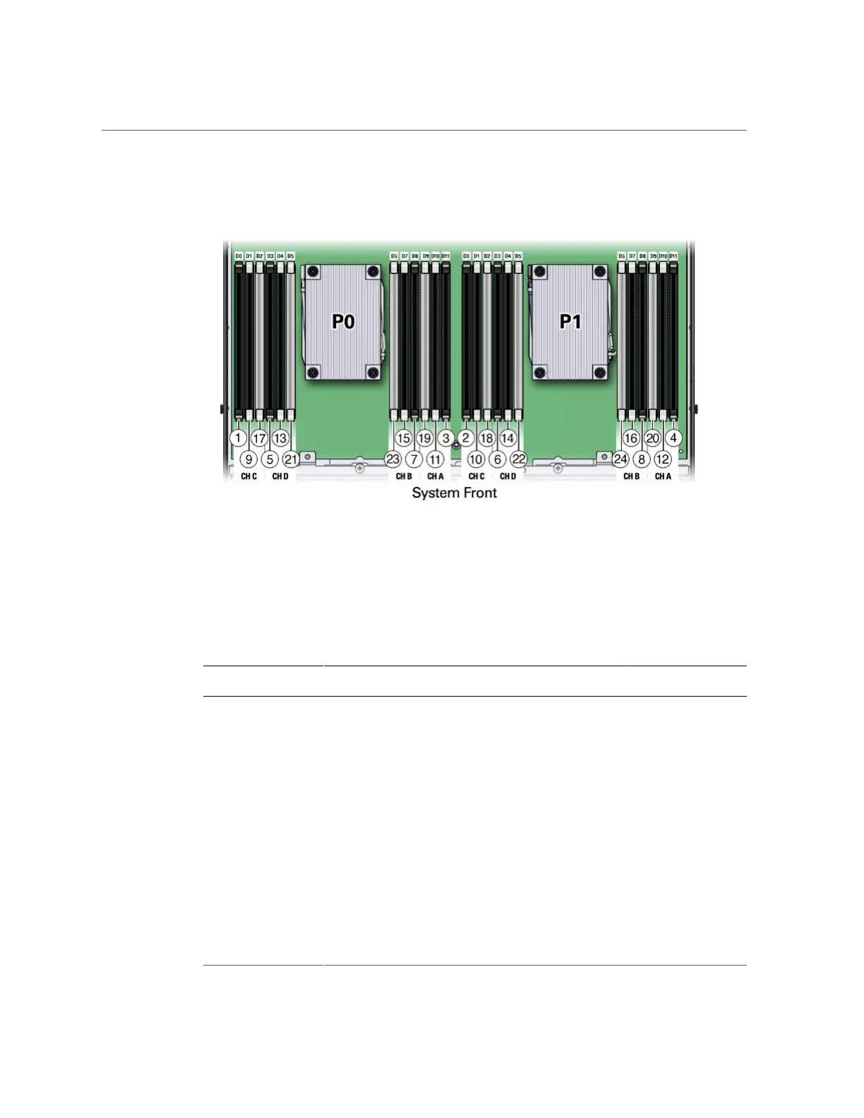
FIGURE 18
DIMM Population Order for Dual-Processor Systems
The following table describes the proper order in which to install DIMMs in a dual-processor
system using the numbered callouts in the above figure, the memory channels labels (Ch A
through Ch D), and the DIMM socket labels (D0 through D11).
TABLE 13
DIMM Population Order for Dual-Processor Systems
Population Order DIMM Sockets for Processor
0 (P0)
DIMM Sockets for Processor 1
(P1)
Memory Channels
Fill the black sockets first (alternating between processor 0 and processor 1)
First Fill D0 first Then fill D0 Ch C
Second Fill D11 first Then fill D11 Ch A
Third Fill D3 first Then fill D3 Ch D
Fourth Fill D8 first Then fill D8 Ch B
Then fill the black sockets with white tabs (alternating between processor 0 and processor 1)
Fifth Fill D1 first Then fill D1 Ch C
Sixth Fill D10 first Then fill D10 Ch A
Seventh Fill D4 first Then fill D4 Ch D
Eighth Fill D7 first Then fill D7 Ch B
Then fill the white sockets (alternating between processor 0 and processor 1)
Ninth Fill D2 first Then fill D2 Ch C
Tenth Fill D9 first Then fill D9 Ch A
Eleventh Fill D5 first Then fill D5 Ch D