338
DP-2330/3030
MAR 2005
Ver.2.1
DP-2310/3010
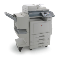
(13) Secure the Ground Harness with 1 Screw
(XTW3+6LFC).
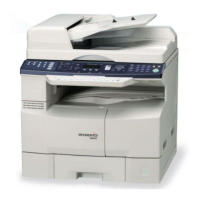
(14) Reinstall the HP Cover.
(15) Secure the HP Cover with 2 Screws.
(16) Connect one Harness to Intermediate
Connector.
(17) Route the FNS Harness through the upper hole
to the main PC Board area.
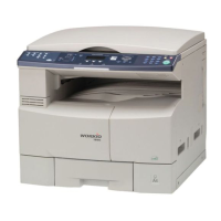
(18) Remove 4 Silver Screws.
(19) Open the Rear Cover.
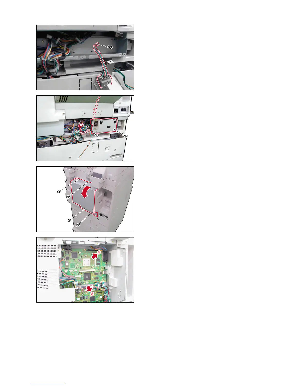
Caution:
If the Red LEDs on the SC and SPC PC Boards
are ON, the Power is still ON.
Please read these Installation Instructions once
again.

 Loading...