LIFEPAK 15 Monitor/Defibrillator
Service Manual
Replacement Procedures
NIBP (A21)/CO2 (A23) Module Replacement
Section Menu Section Contents Procedures Back Index
292
8
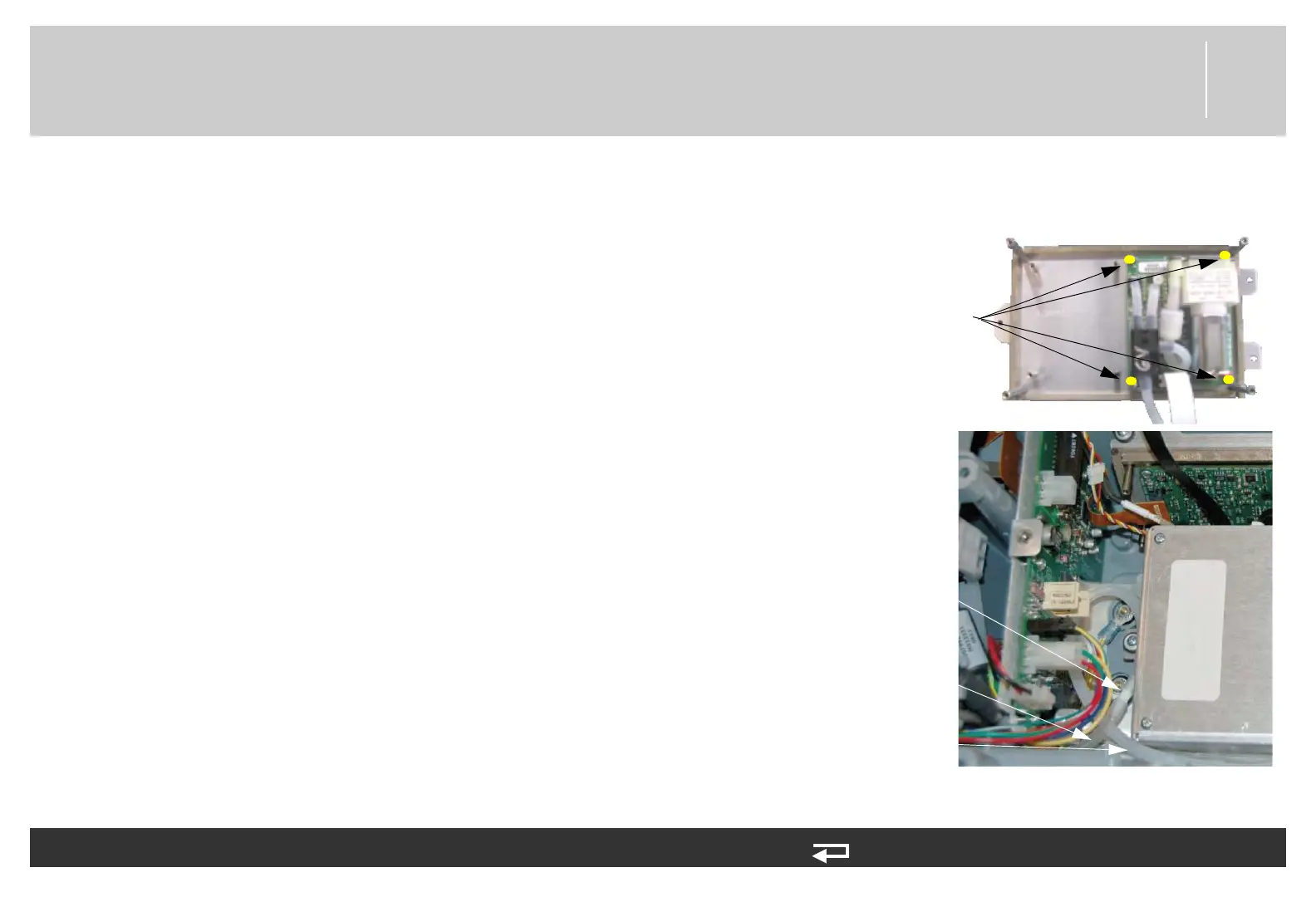
Installing the NIBP (A21)/CO2 (A23) Modules
To install the A21 NIBP, A23 CO2, and SpO2 PCBs: 12 steps, (Page 1 of 6)
1. For NIBP option:
NOTE: When replacing the NIBP module, use NIBP MAXIQ 5.2
Repair Kit (MIN 3305431-531) (p. 494) or NIBP Module
Repair Kit (MIN 3305431-000) (p. 495).
a. Attach the NIBP module sub-assembly (3317965-002 or 3206268-
011) to the OEM bracket (3206965-001) with four new screws
(202253-760); torque to 4 in-lb.
b. Connect the OEM PCB/NIBP module cable to the A21 NIBP PCB at
J2.
c. Route cable and tubing as shown and ensure that the cable and
tubing are not pinched.
d. Connect the NIBP hose from the module to the inlet fitting. Route
excess tubing as shown. Ensure that the NIBP tubing is routed
through the hole in the bracket cover.
NIBP option only
screws (4 places)
NIBP tube
from module
Figure 8.86—NIBP module
NIBP tube
inlet
NIBP tube
connection